8 charging circuit, 1 alternator, Charging circuit – JLG 4017 Service Manual User Manual
Page 136: Alternator, Caution
Electrical System
9.16
4017
9.8
CHARGING CIRCUIT
If the engine alternator charging warning indicator
illuminates, perform the following checks:
1. Check the all battery cable connections at the
battery, and verify that they are clean and tight.
2. Check the external alternator wiring and
connections, and verify that they are in good
condition.
3. Check the fan belt condition and tension. (Refer to
the Perkins Service Manual.)Verify that the
alternator mounting hardware is tight.
4. Run the engine and check the alternator for noise. A
loose drive pulley, loose mounting hardware, worn or
dirty internal alternator bearings, a defective stator
or defective diodes can cause noise. Replace a worn
or defective alternator.
5. For additional information on the charging circuit
refer to Section 9.5, “Electrical System Schematics.”
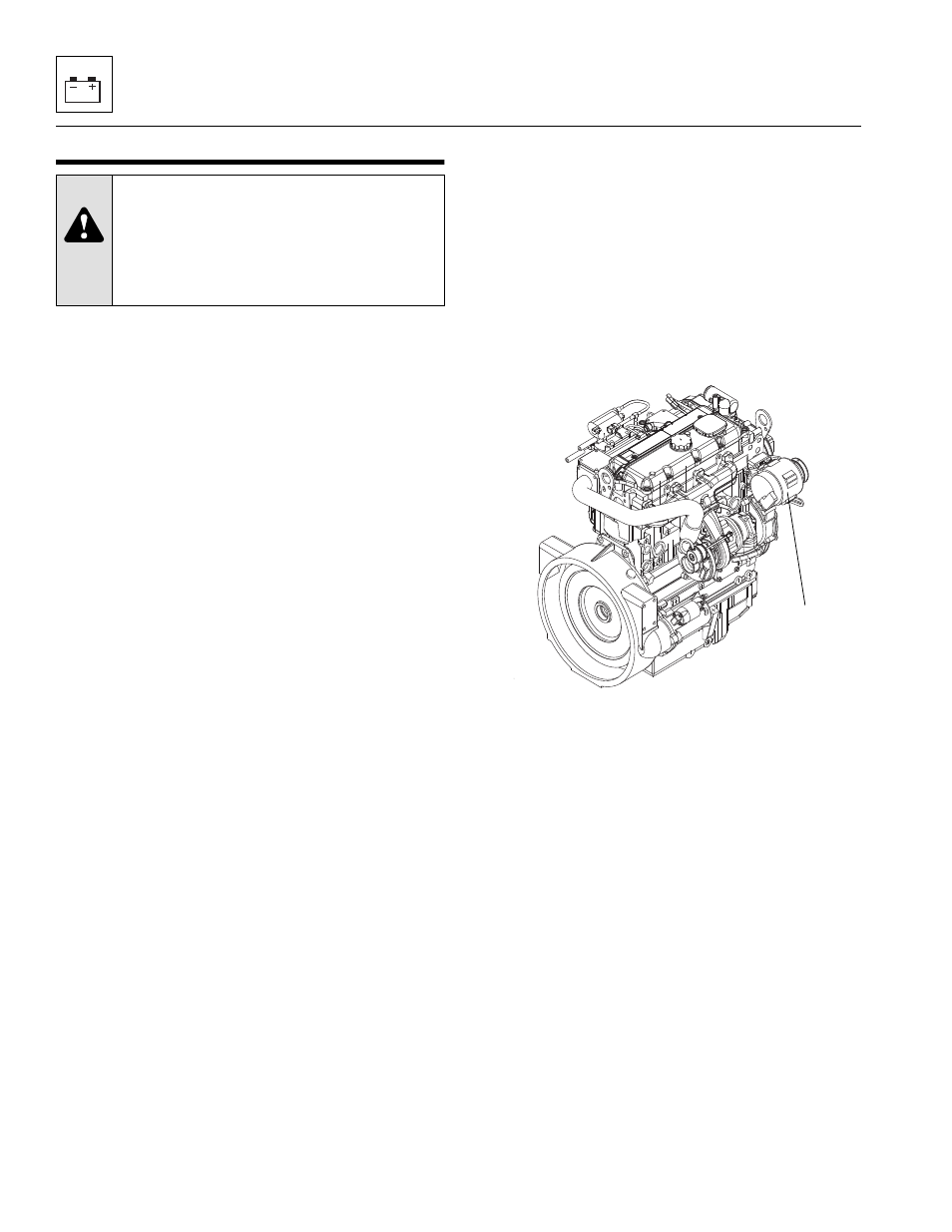
9.8.1
Alternator
a. Alternator Removal
1. Open the engine cover.
2. Disconnect the negative (-) battery cable at the
negative (-) battery terminal.
3. Loosen both alternator (1) mounting bolts and pivot
alternator in.
4. With the fan belt now being loose, remove the belt
from the engine.
Note: Record how the alternator is installed to ensure
correct installation later.
5. Label and disconnect the B+, D+,W and ground wire
leads.
6. Remove the lower mounting capscrew (3) securing
the alternator to the lower mounting hole on the
engine.
7. While supporting the alternator with one hand,
remove the upper (longer) mounting capscrew (4)
from the upper alternator mount. Remove the
alternator from the machine.
CAUTION:
When doing welding
anywhere on the machine disconnect the wire
harness from the ESX Control Module
mounted under the operators seat and
disconnect both cables from the battery and
clamp both cables together.
MZ0150
1