4 joystick assembly, Joystick assembly – JLG 4017 Service Manual User Manual
Page 57
4.5
4017
Cab and Covers
6. Remove the hex jam nut and flat washer securing
the throttle cable to the throttle pedal assembly.
7. Remove the clip/pin from the fork link.
8. Remove the throttle pedal assembly from the cab.
b. Throttle Pedal Installation
1. Install the hex jam nut and flat washer onto the end
of the throttle cable. Secure the cable to the throttle
pedal. Secure the cable to the throttle pedal, with the
clip/pin.
2. Align the throttle pedal assembly with its mount
holes in the cab floor.
3. Install three capscrews securing the throttle pedal
assembly to the cab floor. Torque the capscrews to
12 Nm (9 lb-ft).
4. Connect the battery negative (-) cable to the battery
negative (-) terminal.
5. Close and secure the engine cover.
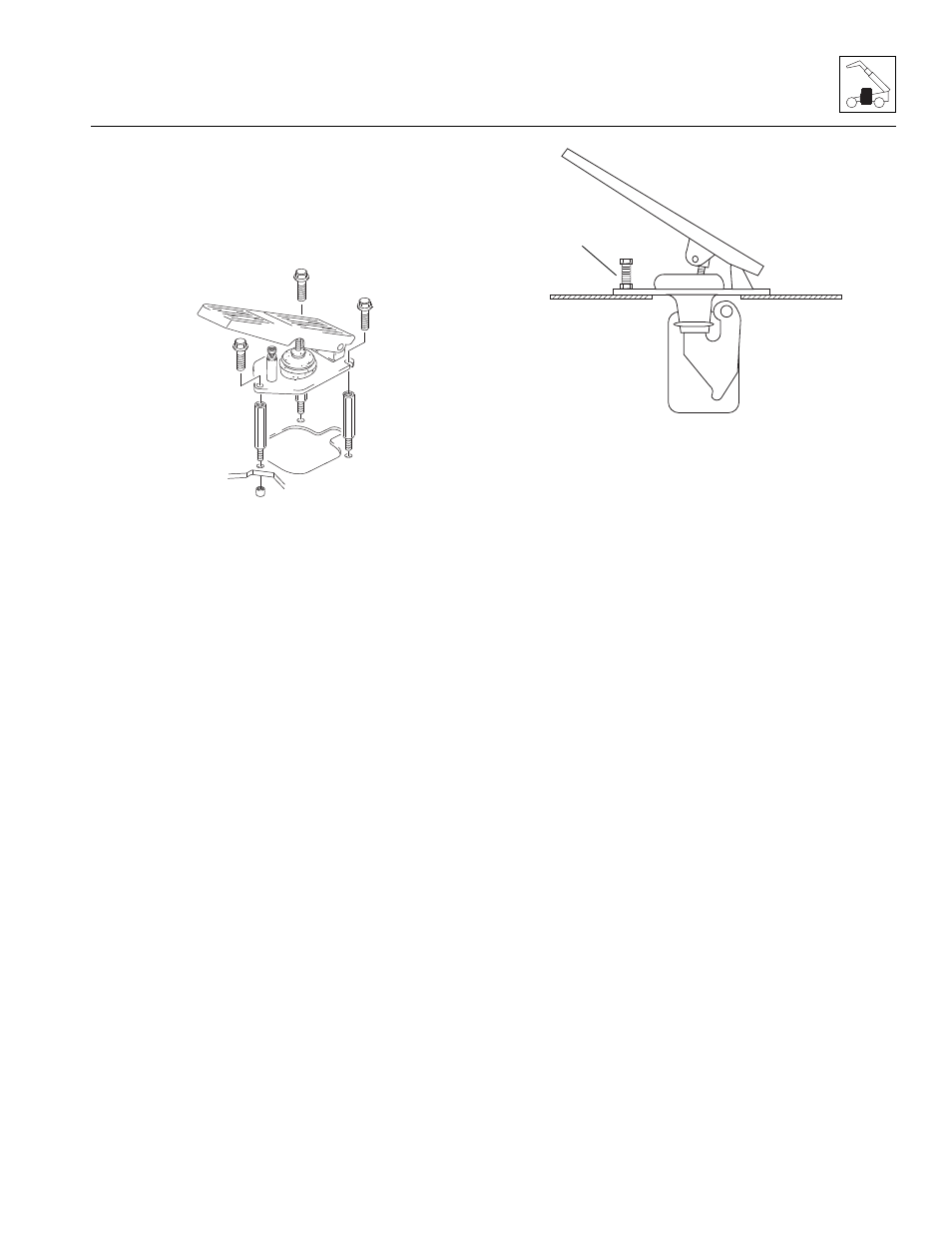
c. Throttle Adjustment
1. From within the cab, lightly depress the accelerator
pedal to the full-throttle position. As needed, adjust the
limit-stop screw (1) until it touches the pedal. Tighten
the locknut to 13,6-14,1 Nm (120-125 lb-in).
IMPORTANT: During the full throttle check:
• DO NOT operate any hydraulic function.
• DO NOT steer or apply any pressure to the steer-
ing wheel.
• Keep the transmission in (N) NEUTRAL.
2. Check the engine rpm at full throttle. If the rpm is not
2200 +/- 50 rpm, readjust the throttle limit-stop screw
at the throttle pedal within the cab.
4.3.4
Joystick Assembly
a. Joystick Assembly Removal
1. Park the machine on a firm, level surface, fully
retract the boom, lower the boom, place the
transmission control lever in the (N) NEUTRAL,
engage the park brake and turn the ignition OFF.
2. Place an Accident Prevention Tag on both the
ignition key switch and steering wheel, stating that
the machine should not be operated.
3. Open the engine cover. Allow the system fluids to
cool.
4. Remove the battery negative (-) cable from the
battery negative (-) terminal.
5. Remove two capscrews. Remove the bottom
cover.Disconnect the electrical connections and
remove the four self-tapping screws from the bottom
of the joystick assembly.
6. Remove the joystick assembly.
MZ0460
MZ0470
1