3 park brake valve, Park brake valve – JLG 4017 Service Manual User Manual
Page 114
Hydraulic System
8.14
4017
b. Service Brake Valve Installation
1. Install the service brake valve with the four
lockwashers and four capscrews to mount the brake
valve to the steering column support.
2. Align the yoke on the brake valve with the brake
pedal arm. Insert the pin and clip into place being
sure there is a small amount of play between the
pedal and the plunger.
Note: ALWAYS replace seals, o-rings, gaskets, etc.,
with new parts to help ensure proper sealing and
operation. Lubricate seals and o-rings with clean
hydraulic oil.
3. Use new oiled o-rings as required. Uncap and
reattach and secure all valves, hoses, clamps, etc.
4. Check the routing of all hoses, and tubing for sharp
bends or interference with any rotating members,
and install tie wraps and/or protective conduit as
required. Tighten all tube and hose clamps.
5. Start the engine and run at approximately one-third
to one-half throttle for about one minute, without
moving the machine or operating any hydraulic
functions.
6. Inspect the service brake valve and connections for
leaks, and check the level of the hydraulic fluid in the
reservoir. Shut the engine OFF.
7. Wipe up any hydraulic fluid spillage in, on, near and
around the machine, work area and tools.
8. Close and secure the engine cover.
c. Brake Test
Carefully bleed the brake lines as soon as the brake valve
is installed in the machine. Air in the system will not allow
the brakes to apply properly. There are four brake
bleeder locations on the front axle. The outside bleeders
are for the park brake, the inside bleeders are for the
service brakes. There are two service brake bleeders on
the rear axle. Work with an assistant to perform this
procedure.
1. Place the transmission control lever in (N)
NEUTRAL, engage the park brake, and start the
engine.
2. Remove the plastic cap from the left front brake
bleeder. Attach one end of a length of transparent
tubing over the brake bleeder. Place the other end of
this tubing in a suitable transparent container that is
partially filled with hydraulic oil. The end of the tubing
must be below the oil level in the container.
3. DO NOT open the brake bleeder without holding the
tubing firmly on the bleeder. There is pressure at the
brakes. Carefully open the bleeder with a 12 mm
wrench. Have the assistant depress the brake pedal.
Close the brake bleeder when air bubbles no longer
appear in the oil. Release the brake pedal. Remove
the tubing from the brake bleeder.
4. Repeat Steps 2 and 3 for the right front brake.
5. Repeat Steps 2,3 and 4 for the rear axle brakes.
6. Install a vacuum pump on the brake reservoir and
remove the remainder of the trapped air from the
brake system.
7. Check brake fluid level and add if necessary using
ATF fluid.
8. Conduct a pressure and function check of the
service brake. Refer to Section 8.4.1, “Hydraulic
Pressures.”
8.7.3
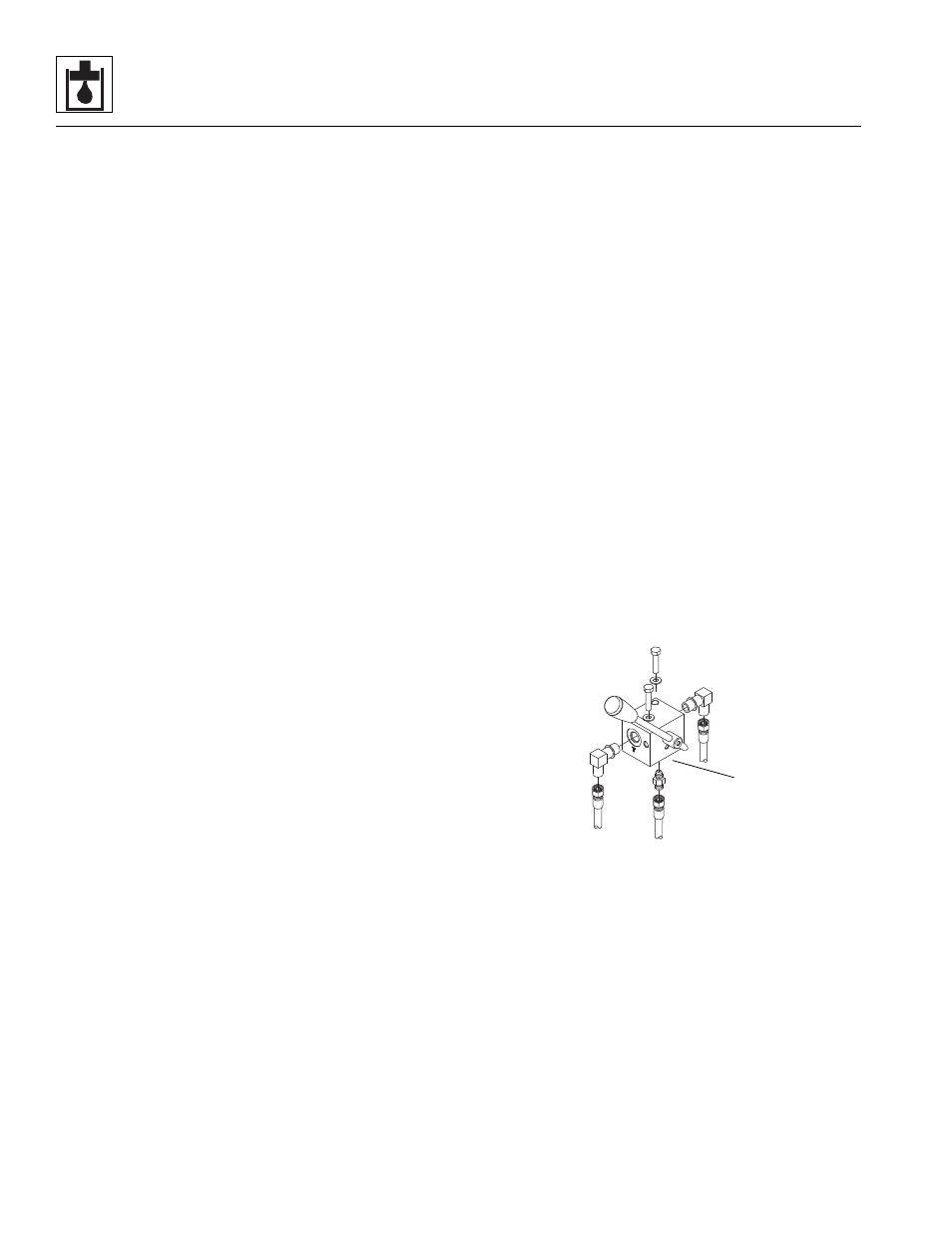
Park Brake Valve
The park brake valve (1) is secured with two capscrews
and lockwashers at the left side of the seat base.
The park brake is part of the front axle only. Refer to Section
5.3, “Axle Assemblies,” for further information.
a. Park Brake Removal
1. Park the machine on a firm, level surface, lower
boom, place the transmission control lever in (N)
NEUTRAL, engage the park brake and shut the
engine OFF.
2. Place an Accident Prevention Tag on both the
ignition key switch and the steering wheel, stating
that the machine should not be operated.
3. Open the engine cover. Allow the hydraulic fluid to
cool.
4. Loosen and remove the three bolts and washers
holding the park brake valve cover. Remove the
cover.
MZ0350
1