6 hose carrier assembly, 1 hose carrier assembly removal, Hose carrier assembly – JLG 4017 Service Manual User Manual
Page 42: Hose carrier assembly removal
Boom
3.18
4017
4. Start the machine and extend and retract the boom
sections two or three times. Fully retract the boom
and measure the distance between the boom
sections.
5. If the measurements are within the tolerance, tighten
the locknuts on the chain clevises. If more
adjustment is needed, refer to paragraph a. or b. and
repeat procedure until the proper boom section
dimensions is achieved.
6. With the boom sections within the proper tolerance,
start the machine, lower the outriggers if necessary
and extend the boom to maximum extension.
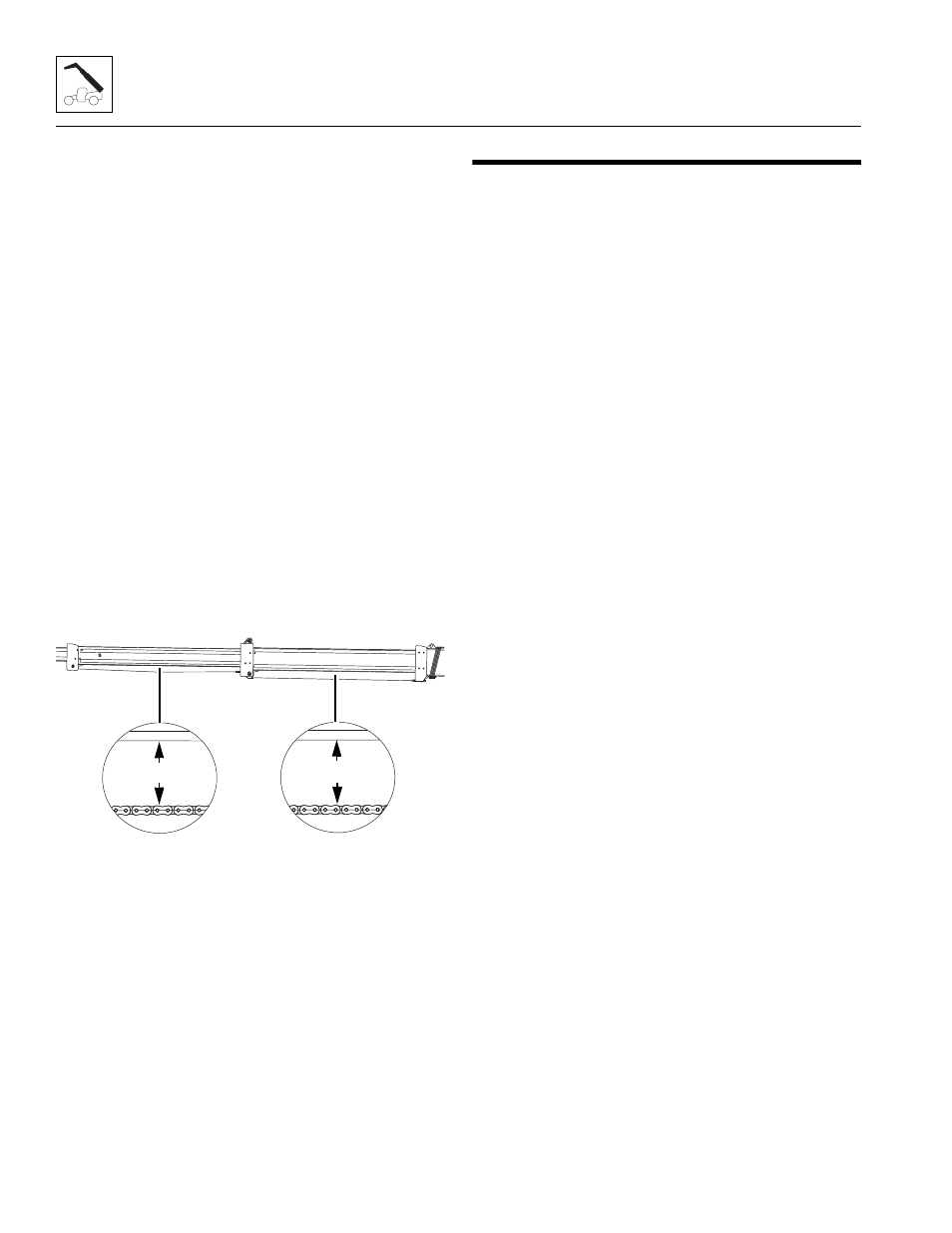
7. Shut the machine off and measure the distance
between the top of both extend chains and the
bottom of the second and third boom sections at the
center of each boom section.
8. The distance (2) between the top of the extend
chains and the bottom of the second boom section
should be approximately 180 mm (7 in). The
distance (2) between the top of the extend chains
and the bottom of the third boom section should be
approximately 120 mm (4.75 in).
Note: If the second boom section to the third boom
section separation distance cannot be achieved, contact
the local JLG distributor or the JLG Service Department.
3.6
HOSE CARRIER ASSEMBLY
3.6.1
Hose Carrier Assembly Removal
1. Remove any attachment from the quick switch
assembly. (Refer to Section 3.8.1, “Connecting with
a Mechanical Quick Switch Device.”)
2. Park the machine on a hard, level surface. Be sure
there is enough room in front and rear of the
machine to extend the boom sections and to be able
to removed the hose carrier from the rear of the
boom assembly.
3. Fully extend the boom and raise the boom to a
horizontal position. Place the transmission control
lever in (N) NEUTRAL, engage the park brake
switch.
4. Retract the boom until the rear hose carrier
mounting bolts on the fourth boom section are
accessible through each side of the third boom
section access holes. Shut off the machine and
remove the bolts.
5. Start the machine and retract the boom until the
middle set of hose carrier bolts on the fourth boom
section are accessible through the third boom
section access holes. Shut the engine OFF and
remove the bolts.
6. Start the engine and retract the boom until the front
set of hose carrier bolts on the fourth boom section
are just in front of the front of the third boom section.
Shut the engine OFF and remove the bolts.
7. Start the engine and slowly retract the boom
sections completely.
8. Shut the engine OFF and place an Accident
Prevention Tag on both the ignition key switch and
the steering wheel, stating that the machine should
not be operated.
9. Relieve any trapped pressure in the tilt hydraulic
system by using the handle provided or a 9mm
wrench and move the double nut on the side of the
main control valve tilt section back and forth. Repeat
on the auxiliary valve section.
10. Locate the two hoses attached to the barrel of the tilt
cylinder inside the boomhead.
11. Label and remove the hoses from the elbow fittings
on the tilt cylinder (1). Plug the hose ends and cap
the elbow fittings on the tilt cylinder to prevent dirt
and debris from entering the hydraulic system.
MZ1220
120mm - 4.75in
180mm - 7in
2