Main assembly -24, Timing marks -24 – JLG 24RS Service Manual User Manual
Page 62
SECTION 3 - CHASSIS & TURNTABLE
3-24
– JLG Lift –
3121287
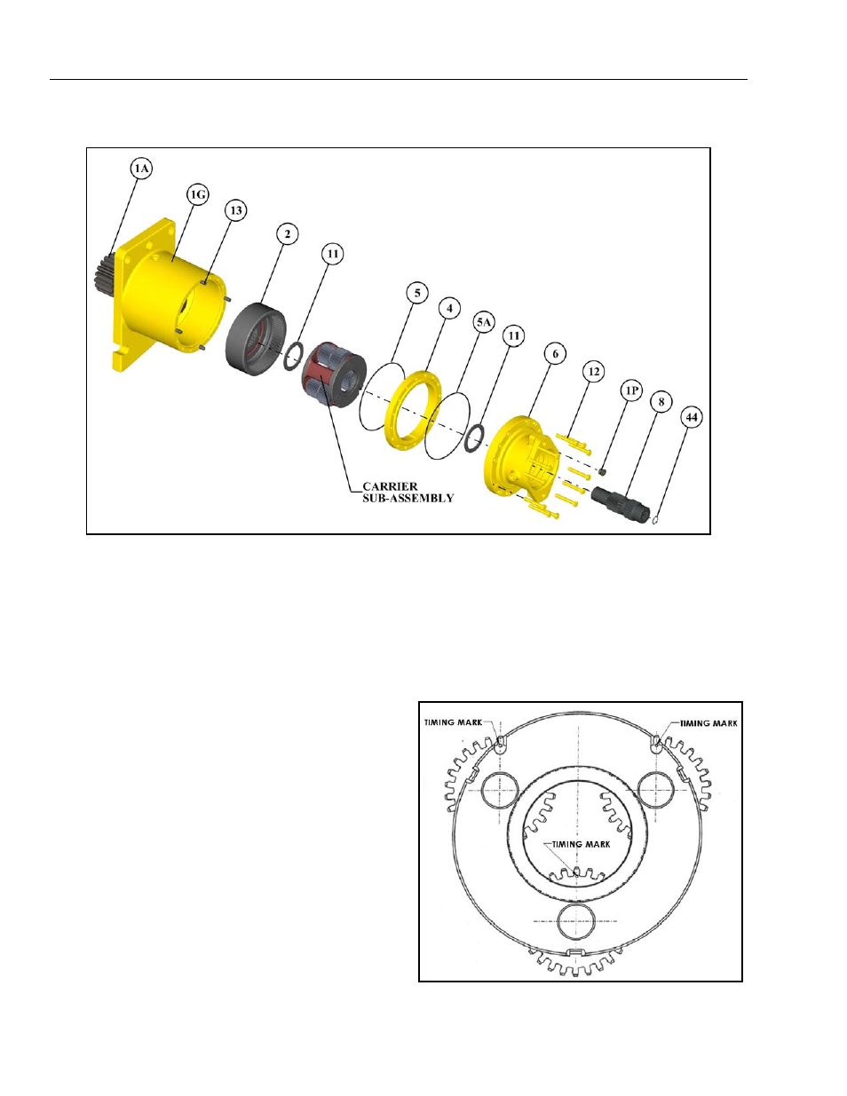
MAIN ASSEMBLY
1.
Slightly tap the internal gear (2) with the spline side
down onto the output shaft (1A) splines to ensure the
internal gear (2) is properly seated.
2.
Grease and install the o-ring (5) onto the housing (1G) o-
ring groove.
3.
Grease and install thrust spacer (11) into the counter-
bore of the carrier sub-assembly on smaller diameter
cluster gear side. The grease should hold the thrust
spacer (11) in place for assembly.
4.
Place the carrier sub-assembly onto a table oriented as
shown in Figure 3-17., with the large end of the cluster
gear (3F) facing up. Position all three punch-marks on
the face of the large gears at 12 o’clock. Timing marks on
the two upper cluster gears will be visible through the
slots in the carrier if the cluster gears are correctly
marked. Secure the gear teeth using a timing fixture.
1A Output Shaft
1G Housing
1P Pipe Plug
2 Internal Gear
4 Ring Gear
6 Brake Housing
8 Sun Gear
5 O-ring
5A O-ring
11 Thrust Washer
12 Bolts
13 Dowel Pin
44 Internal Retaining Ring
Figure 3-16. Main Assembly
Figure 3-17. Timing Marks