Shaft seal, roller bearing and shaft replacement, Shaft assembly -44, Positioning seal in seal carrier -44 – JLG 24RS Service Manual User Manual
Page 168
SECTION 5 - HYDRAULICS
5-44
– JLG Lift –
3121287
Shaft Seal, Roller Bearing and Shaft Replacement
The shaft assembly is serviceable without disassembling the
pump. Orient the pump on
the work surface so the shaft is pointing to the side.
REMOVAL
1.
Unwind the spiral ring (J300) from the housing to
release the shaft/seal/bearing subassembly.
2.
Pry on the lip of the seal carrier (J275) to dislodge it from
the pump. Remove the seal carrier. Remove and discard
O-ring (J260). Press the seal (J250) out of the carrier and
discard.
3.
Pull the shaft (J100) with bearing (J150) out of the
pump. If necessary, tap lightly on the shaft to dislodge it
from the cylinder block.
DO NOT DAMAGE THE HOUSING BORE, SHAFT OR BEARING WHEN REMOVING
THE SHAFT AND SHAFT SEAL.
4.
Remove the retaining ring (J200) using retaining ring
pliers. Press the bearing off the shaft.
INSPECTION
1.
Inspect the shaft journals for wear, scratching, and pits.
Check the splines for fretting; replace if damaged.
Rotate the bearing, if it does not rotate smoothly,
replace it.
REASSEMBLY
1.
Press the bearing (J150) onto the shaft (J100) and
replace the retaining ring (J200). Ensure the retaining
ring diameter is less than 38.84 mm [1.53 in] when
installed on the shaft.
2.
Install the shaft/bearing assembly into the pump.
3.
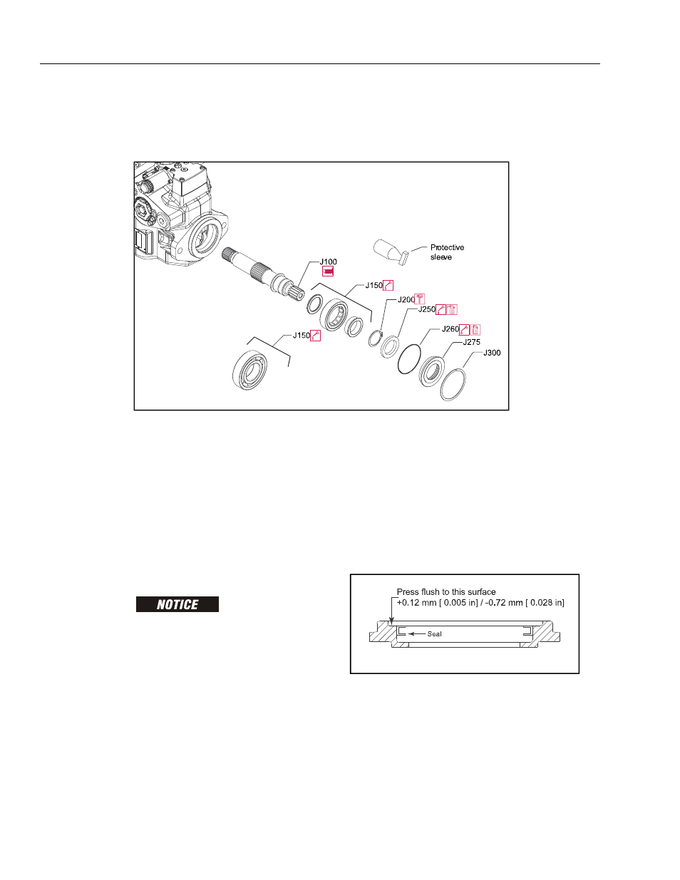
Lubricate and install a new O-ring (J260) onto seal car-
rier (J275). Press a new seal (J250) into the seal carrier.
Press the seal until it is flush within +0.12mm [0.005 in]
or -0.72 mm [0.0028 in] of the inside lip of the carrier: see
illustration.
4.
Cover the shaft with a protective sleeve while installing
the seal carrier. Hand press the seal carrier into the hous-
ing. Ensure the seal carrier clears the spiral ring groove
in the housing. Remove the protective sleeve.
5.
Wind the spiral ring into the housing. Ensure the inside
diameter of the spiral ring is greater than 68 mm [2.677
in] after installation.
Figure 5-42. Shaft Assembly
Figure 5-43. Positioning Seal in Seal Carrier