Charge check / hprv, Charge check / hprv -46, Torque sequence -46 – JLG 24RS Service Manual User Manual
Page 170: Auxiliary pads -46, High pressure relief valves -46, Cover screw torque -46
SECTION 5 - HYDRAULICS
5-46
– JLG Lift –
3121287
6.
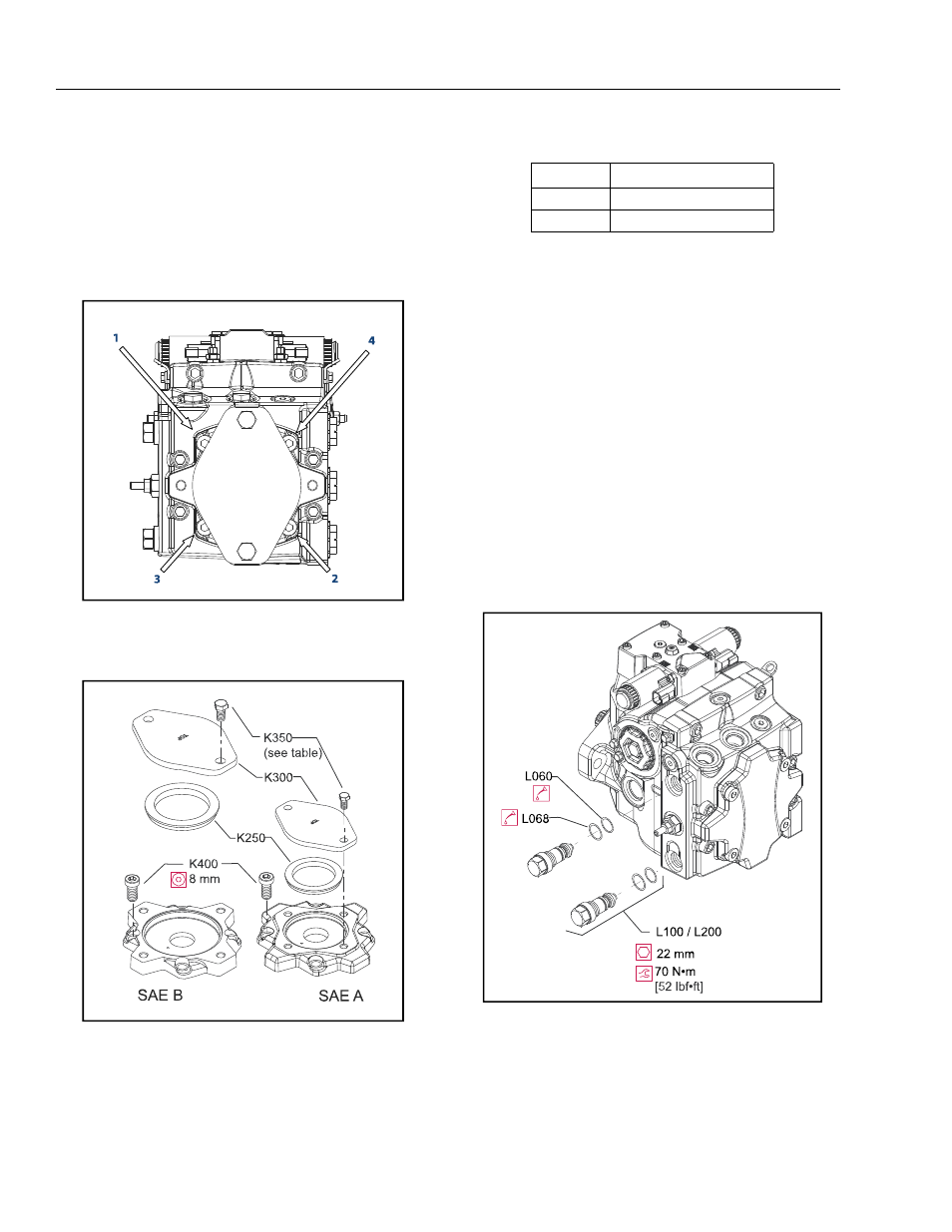
Install the thrust washer (K500). Coated side goes
toward charge pump coupling (K200).
7.
Install a new cover gasket. (K150). If removed, install
guide pins (K450).
8.
Install the auxiliary pad or charge pump cover and cap
screws. Using a 8mm internal hex wrench, torque the
cap screws (K400) to 92 N•m [68 lbf•ft]. Torque in
sequence below.
9.
Reinstall auxiliary pump or pad seal (K250) and shipping
cover ((K300).
Charge Check / HPRV
REMOVAL
1.
Using a hex wrench shown in the table below, remove
the HPRVs (L150). Remove and discard the O-rings
(L060) and backup rings (L068).
INSPECTION
1.
Inspect the sealing surfaces in the pump for nicks or
scratches. Check the valves for damage. Replace any
damaged components.
REASSEMBLY
1.
Lubricate and install new backup rings (L068) and O-
rings (L060).
2.
Install HPRVs. Torque to the value in the table below.
3.
Operate the vehicle/machine through full range of con-
trols to ensure proper operation. Check for leaks.
Figure 5-45. Torque Sequence
Figure 5-46. Auxiliary Pads
Table 5-11. Cover Screw Torque
Cover Pad
Wrench size and Torque
A
17 mm 48 N•m [35 lbf•ft]
B
18 mm 77 N•m [58 lbf•ft]
Figure 5-47. High Pressure Relief Valves