10 cab heater/air conditioning controls, 4 cab removal, Cab removal – JLG 4013PS Service Manual User Manual
Page 71: Cab heater/air conditioning controls
4-9
3508PS, 3509PS, 3512PS, 3513PS, 4008PS, 4009PS, 4012PS, 4013PS, 4017PS, 40.8, 40.9
Cab and Covers
9. Replace the belly pan.
10. Close and secure the engine cover.
11. Remove the Do Not Operate Tags from both the
ignition key switch and the steering wheel.
4.3.10
Cab Heater/Air Conditioning Controls
a. Cab Heater Controls Removal
1. Park the machine on a firm, level surface, level the
machine, fully retract the boom, lower the boom,
place the transmission control lever in
(N) NEUTRAL, engage the park brake and shut the
engine OFF.
2. Place a Do Not Operate Tag on both the ignition key
switch and the steering wheel, stating that the
machine should not be operated.
3. Open the engine cover. Allow the system fluids to
cool.
4. Properly disconnect the battery.
5. Remove the plastic side cover in the cab to gain
access to the control cables and electronics. If
necessary, remove the seat for more accessibility.
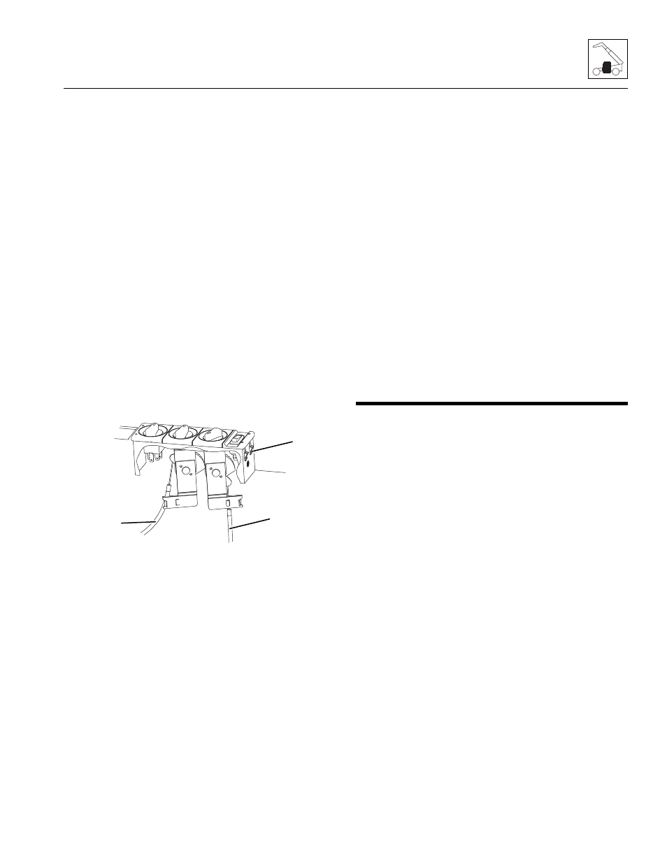
6. Label and disconnect the control cables (8) attached
to the control knob mechanisms.
7. Label and disconnect the electrical connectors
attached to the control box.
8. Depress the side clips (9) and push the control box
through the dash panel.
b. Disassembly
DO NOT disassemble the cab heater and fan controls.
The controls are not serviceable. Replace controls if
found to be defective.
c. Installation and Testing
1. Install the control box into the dash panel until the
side clips firmly hold the box.
2. Connect the previously labeled electrical connectors
to the appropriate locations.
3. Connect the previously labeled control cables to the
appropriate control knob mechanisms.
4. Properly connect the battery.
5. Turn the ignition key to the ON position and check
the control functions.
6. Start the machine and allow engine to warm to
operating temperature. Check heat control at
different levels.
7. Install the plastic side cover. If necessary, install the
seat.
8. Close and secure the engine cover.
9. Remove the Do Not Operate Tags from both the
ignition key switch and the steering wheel.
4.4
CAB REMOVAL
Note: To help ensure safety and optimum performance,
replace the cab if it is damaged. Refer to the appropriate
parts manual for ordering information.
Before performing any inspection, maintenance or
service operation, thoroughly clean the machine. DO
NOT spray water or cleaning solution in, on, near or
around the operator dash panels and electrical
components.
Inspect the cab, its welds and mounts. If modification,
damage, a cracked weld and/or fatigued metal is
discovered, replace the cab. Contact your local authorized
service distributor with any questions about the suitability
or condition of a cab.
Note: Remove and label cab components as needed
before removing the cab from the machine. Label,
disconnect and cap hydraulic hoses. Transfer cab parts
to the replacement cab after the replacement cab is
securely mounted on the machine.
1. Park the machine on a firm, level surface, level the
machine. Allow sufficient overhead and side
clearance for cab removal. Fully retract the boom,
lower the boom, place the transmission control lever
in (N) NEUTRAL, engage the park brake and shut
the engine OFF.
2. Block the wheels.
3. Open the engine cover. Allow the system fluids to
cool.
MAM0310
8
8
9