5 parking brake (8, 9, 12 & 13m), Parking brake (8, 9, 12 & 13m) – JLG 4013PS Service Manual User Manual
Page 68
Cab and Covers
4-6
3508PS, 3509PS, 3512PS, 3513PS, 4008PS, 4009PS, 4012PS, 4013PS, 4017PS, 40.8, 40.9
b. Joystick Assembly Installation
1. Set the joystick assembly into the armrest support.
2. Install the four self-tapping screws. Connect the
electrical connections.
3. Properly connect the battery.
4. Test the boom joystick functions:
a. Move the joystick handle rearward, activating the
boom lift function. The boom should RISE.
b. Move the joystick handle forward, activating the
boom lower function. The boom should LOWER.
c. Move the joystick handle to the right, activating
the boom extend function. The boom should
EXTEND.
d. Move the joystick handle to the left, activating the
boom retract function. The boom should
RETRACT.
e. Move the joystick rocker switch forward
activating the boom extend function. The boom
should EXTEND.
5. Install the bottom cover.
6. Close and secure the engine cover.
7. Remove the Do Not Operate Tags from both the
ignition key switch and the steering wheel.
4.3.5
Parking Brake (8, 9, 12 & 13M)
a. Park Brake Removal
1. Park the machine on a firm, level surface, level the
machine, fully retract the boom, lower the boom,
place the transmission control lever in (N)
NEUTRAL, engage the park brake and shut the
engine OFF.
2. Place a Do Not Operate Tag on both the ignition key
switch and the steering wheel, stating that the
machine should not be operated.
3. Open the engine cover. Allow the system fluids to
cool.
4. Block the wheels.
5. Properly disconnect the battery.
6. Remove the cover from around the park brake lever.
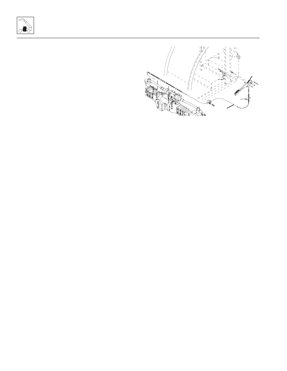
7. Remove the pin attached to the park brake cable (1)
from the park brake lever (2).
8. Remove the bolts holding the park brake lever to the
mounting plate.
9. Loosen the nuts securing the park brake cable to the
mounting plate.
10. Feed the cable end through the bottom of the cab.
11. If necessary, remove the cable clamp from under the
cab.
Note: Record the routing of the park brake cable for
later installation.
12. Remove the cable mounting hardware on the front
axle to free the park brake cable.
b. Park Brake Installation
1. Install the park brake cable on the front axle.
2. Route the park brake cable using the previous
routing path.
3. Feed the cable end through the bottom of the cab.
4. Secure the park brake lever to the mounting plate
using the pre-existing mounting hardware.
5. Secure the park brake cable to the park brake lever
with the pre-existing pin.
6. Connect the park brake electrical connector switch.
7. Properly connect the battery.
8. Test the park brake for proper functionality.
9. With the park brake applied, check the display panel
for the proper indicator light.
10. Reinstall the cover around the park brake lever.
11. Unblock the wheels.
12. Close and secure the engine cover.
13. Remove the Do Not Operate Tags from both the
ignition key switch and the steering wheel.
MZ1490
1
2