1 load stability indicator, Load stability indicator, Warning – JLG 4013PS Service Manual User Manual
Page 174
Electrical System
9-34
3508PS, 3509PS, 3512PS, 3513PS, 4008PS, 4009PS, 4012PS, 4013PS, 4017PS, 40.8, 40.9
a. Boom Retracted Sensor Removal
1. Park the machine on a firm, level surface, level the
machine, fully retract the boom, lower the boom,
place the transmission control lever in (N)
NEUTRAL, engage the park brake and shut the
engine OFF.
2. Place a Do Not Operate Tag on both the ignition key
switch and the steering wheel, stating that the
machine should not be operated.
3. Open the engine cover. Allow the engine to cool.
4. Properly disconnect the battery.
5. Disconnect the boom retracted sensor electrical
connector.
6. Remove the two bolts securing the boom retracted
sensor bracket to the boom.
7. Remove the boom retracted sensor from the sensor
bracket.
b. Boom Retracted Sensor Inspection and
Replacement
Inspect the sensor and the wiring harness connector
terminals for continuity. Replace a defective or faulty
sensor with a new sensor.
c. Boom Retracted Sensor Installation
1. Mount the boom retracted sensor to the boom with
the previously used hardware.
2. Install the sensor into the sensor bracket. Adjust the
sensor to 5 ± 0,5 mm (from the rear of the second
boom section. Tighten the sensor locknut.
3. Plug the electrical connector into the sensor
assembly.
4. Properly connect the battery.
5. Close and secure the engine cover.
6. Remove the Do Not Operate Tag from the ignition
key switch and the steering wheel.
9.15
LOAD STABILITY INDICATOR (LSI) -
8, 9, 12 & 13M Before S/N 1160005993
excluding 1160005949 & 1160005950
17M Before S/N 1160005937 including
1160005952, 1160005960,
1160005963, 1160005966 &
1160005978
9.15.1
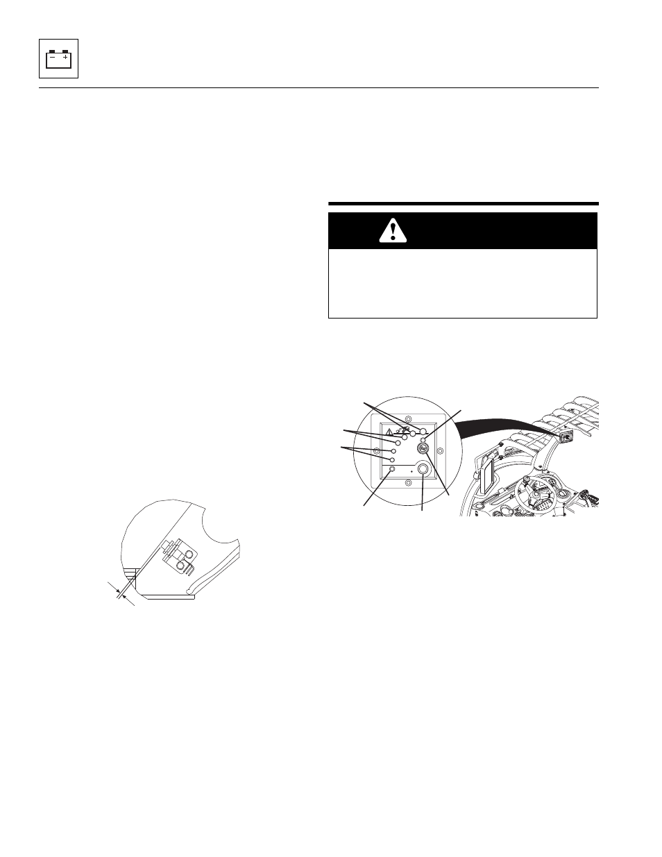
Load Stability Indicator
Note: The Load Stability Indicator is NOT a serviceable
item. The LSI must be inspected and/or replaced by a
qualified dealer or a JLG technician.
The LSI provides visual and audible indication of forward
stability limitations when machine is static on firm, level
surface.
• Green LED (1) will illuminate when LSI power is on.
• When approaching forward stability limitations LEDs
progressively illuminate, green (2), then yellow (3)
and finally red (4).
• The warning buzzer sounds as the first red LED
illuminates.
• As the telehandler reaches forward stability
limitations and the red LED illuminates, the
automatic function cut-out is activated. Certain
functions are disabled (i.e. boom lift, extend, etc).
Retract boom to re-enable functions.
• Press button (5) to disable the warning buzzer.
When disabled, yellow LED (7) will illuminate. If last
red LED illuminates, disable button is overridden
and warning buzzer sounds.
MZ2580
5 ±0,5 mm
WARNING
TIP OVER HAZARD. The LSI considers only
longitudinal stability limitations, observe all operating
parameters. Failure to follow operating parameters of
the telehandler could damage the equipment and/or
cause tip over.
MZ6011
4
3
2
1
5
6
8