8 auxiliary pump (platform equipped models only), 1 auxiliary pump description, 2 auxiliary pump replacement – JLG 4013PS Service Manual User Manual
Page 130: 9 valves and manifolds, 1 main control valve, Auxiliary pump (platform equipped models only), Valves and manifolds, Auxiliary pump description, Auxiliary pump replacement, Main control valve
Hydraulic System
8-20
3508PS, 3509PS, 3512PS, 3513PS, 4008PS, 4009PS, 4012PS, 4013PS, 4017PS, 40.8, 40.9
8.8
AUXILIARY PUMP (PLATFORM
EQUIPPED MODELS ONLY)
8.8.1
Auxiliary Pump Description
The auxiliary pump works as a safety back up for the
platform in case of engine stalling. The pump will allow
the platform to lower without the engine running.
8.8.2
Auxiliary Pump Replacement
a. Auxiliary Pump Removal
1. Park the machine on a firm, level surface, level the
machine, fully retract the boom, lower the boom,
place the transmission control lever in
(N) NEUTRAL, engage the park brake and shut the
engine OFF.
2. Place a Do Not Operate Tag on both the ignition key
switch and the steering wheel, stating that the
machine should not be operated.
3. Open the engine cover. Allow the system fluids to
cool.
4. Properly disconnect the battery.
5. Thoroughly clean the auxiliary pump (2) and
surrounding area, including all hoses and fittings,
before proceeding.
6. Place a suitable container to catch hydraulic oil
drainage beneath the frame.
7. Label, disconnect and cap the hydraulic hoses
attached to the auxiliary pump. Slowly turn hose
fittings to allow any trapped pressure in the hydraulic
system to escape. Call all fittings to prevent dirt and
debris from entering the hydraulic system.
8. Wipe up any hydraulic oil spillage in, on, near and
around the machine and work area.
9. Label and disconnect the electrical connections to
the auxiliary pump.
10. Support the valve and remove the bolts securing the
pump to the engine pod.
11. Remove the pump.
b. Auxiliary Pump Installation
1. Install the pump to its original orientation and secure
in place with the previously used hardware.
2. Connect the previously labeled electrical
connections to the pump.
3. Uncap and connect the previously labeled hydraulic
hoses to the auxiliary pump.
4. Properly connect the battery.
5. Test the pump functions.
6. Close and secure the engine cover.
7. Remove the Do Not Operate Tags from both the
ignition key switch and the steering wheel.
8.9
VALVES AND MANIFOLDS
8.9.1
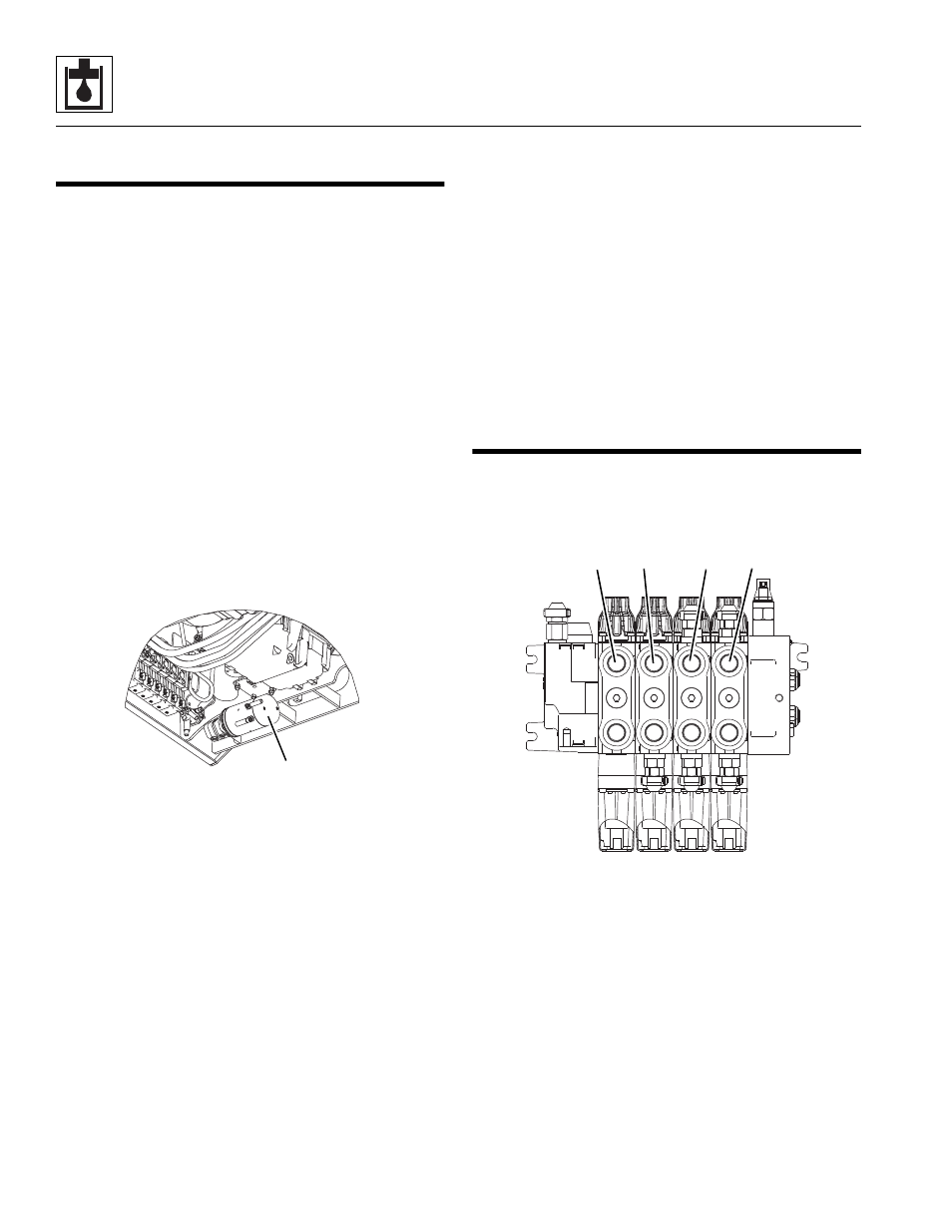
Main Control Valve
The main control valve is mounted on the side rail in the
engine compartment.
The main control valve assembly consists of working
sections with their own valve assemblies, each providing
a specific hydraulic function. Those functions are:
lift/lower (3), extend/retract (4), tilt (5) and auxiliary (6).
a. Main Control Valve Removal
1. Park the machine on a firm, level surface, level the
machine, fully retract the boom, lower the boom,
place the transmission control lever in
(N) NEUTRAL, engage the park brake and shut the
engine OFF.
2. Place a Do Not Operate Tag on both the ignition key
switch and the steering wheel, stating that the
machine should not be operated.
MZ2530
2
MZ2080
6
5
4
3