Infinity supported application 11 – AEM Infinity Supported Applications - Mitsubishi 2006 Evolution IX Engine User Manual
Page 11
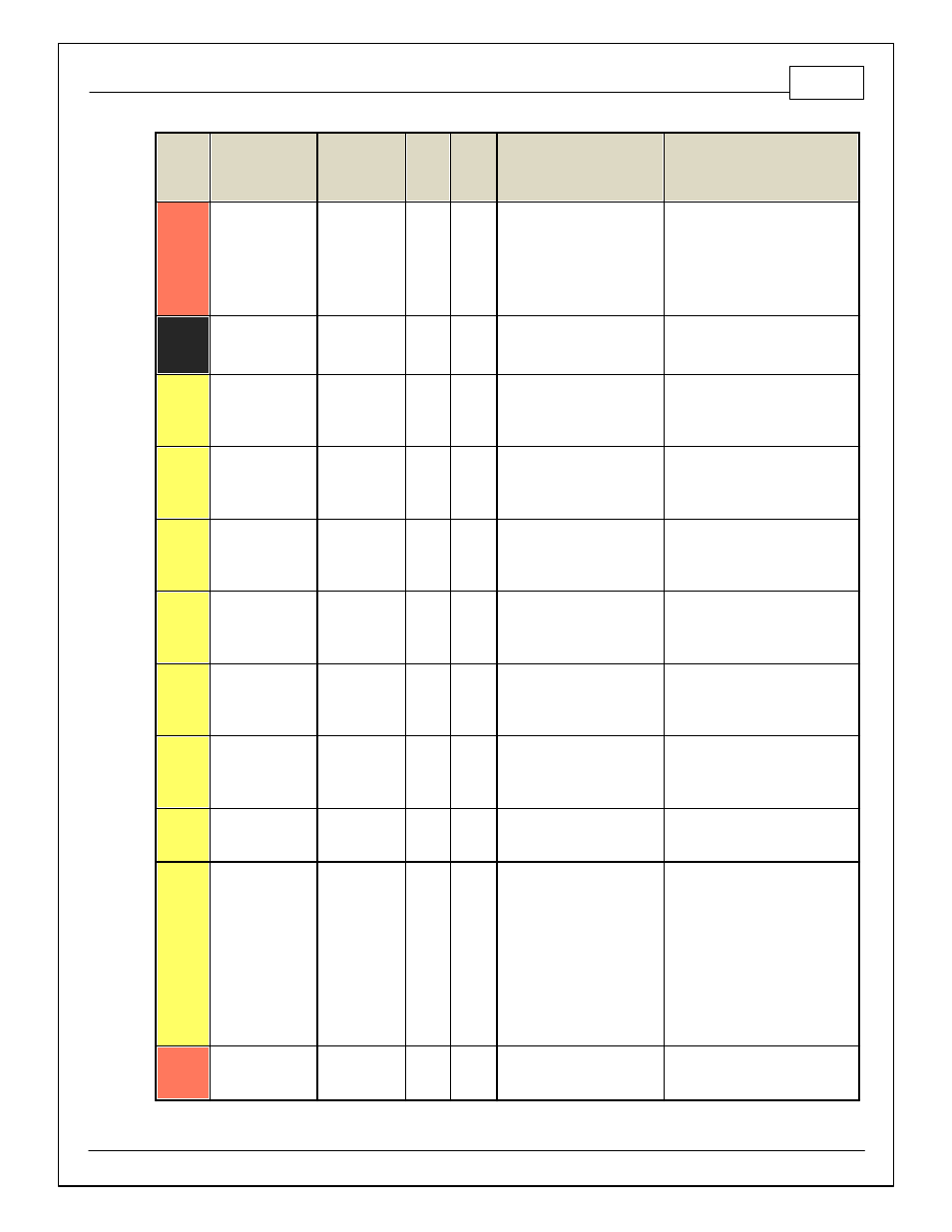
Infinity Supported Application
11
© 2014 AEM Performance Electronics
Infinity
Pin
Hardware
Reference
7100-XXXX-62
7101-XXXX-63
Function
Dest.
Pin
Evo
VIII
Dest.
Pin
Evo IX
Hardware Specification
Notes
C1-9
Flash_Enable
Flash Enable
10K pulldown
Not usually needed f or automatic
f irmware updates through Inf inity
Tuner. If connection errors occur
during update, connect 12 v olts to
this pin bef ore proceeding with
upgrade. Disconnect the 12 v olts
signal af ter the update.
C1-10
+12V_R8C_CPU
Battery Perm
Power
80
60
Dedicated power management
CPU
Full time battery power. MUST be
powered bef ore the ignition switch
input is triggered. (See C1-65.)
C1-11
Coil 4
Coil 4
25 mA max source current
0–5V Falling edge f ire. DO NOT
connect directly to coil primary . Must
use an ignitor OR CDI that accepts a
FALLING edge f ire signal.
C1-12
Coil 3
Coil 3
25 mA max source current
0–5V Falling edge f ire. DO NOT
connect directly to coil primary . Must
use an ignitor OR CDI that accepts a
FALLING edge f ire signal.
C1-13
Coil 2
Coil 2
23
12
25 mA max source current
0–5V Falling edge f ire. DO NOT
connect directly to coil primary . Must
use an ignitor OR CDI that accepts a
FALLING edge f ire signal.
C1-14
Coil 1
Coil 1
10
11
25 mA max source current
0–5V Falling edge f ire. DO NOT
connect directly to coil primary . Must
use an ignitor OR CDI that accepts a
FALLING edge f ire signal.
C1-15
Coil 6
Coil 6
25 mA max source current
0–5V Falling edge f ire. DO NOT
connect directly to coil primary . Must
use an ignitor OR CDI that accepts a
FALLING edge f ire signal.
C1-16
Coil 5
Coil 5
25 mA max source current
0–5V Falling edge f ire. DO NOT
connect directly to coil primary . Must
use an ignitor OR CDI that accepts a
FALLING edge f ire signal.
C1-17
LowsideSwitch_2
Coolant Fan 1
Control
32, 34
30, 31
Lowside switch, 4A max, NO
internal f ly back diode.
See "LowSide Assignment Tables" f or
output assignment.
C1-18
LowsideSwitch_3
MIL Output
36
22
Lowside switch, 4A max with
internal f ly back diode.
Inductiv e load should NOT
hav e f ull time power.
See Wizard page "LowSide
Assignment Tables" f or output
assignment.
MIL Activ ates when any of the
f ollowing f lags are true: ErrorAirTemp,
ErrorBaro, ErrorCoolantTemp,
ErrorEBP, ErrorFuelPressure,
UEGO_0_Diag_error,
UEGO_1_Diag_error,
ErrorMAFAnalog, ErrorMAFDigital,
ErrorMAP, ErrorOilPressure,
ErrorThrottle.
C1-19
AGND_1
Sensor Ground
92
49
Dedicated analog ground
Analog 0–5V sensor ground