Pinouts, Infinity pinout – AEM Infinity Supported Applications - Mitsubishi 2006 Evolution IX Engine User Manual
Page 10
10
© 2014 AEM Performance Electronics
PINOUTS
Infinity Pinout
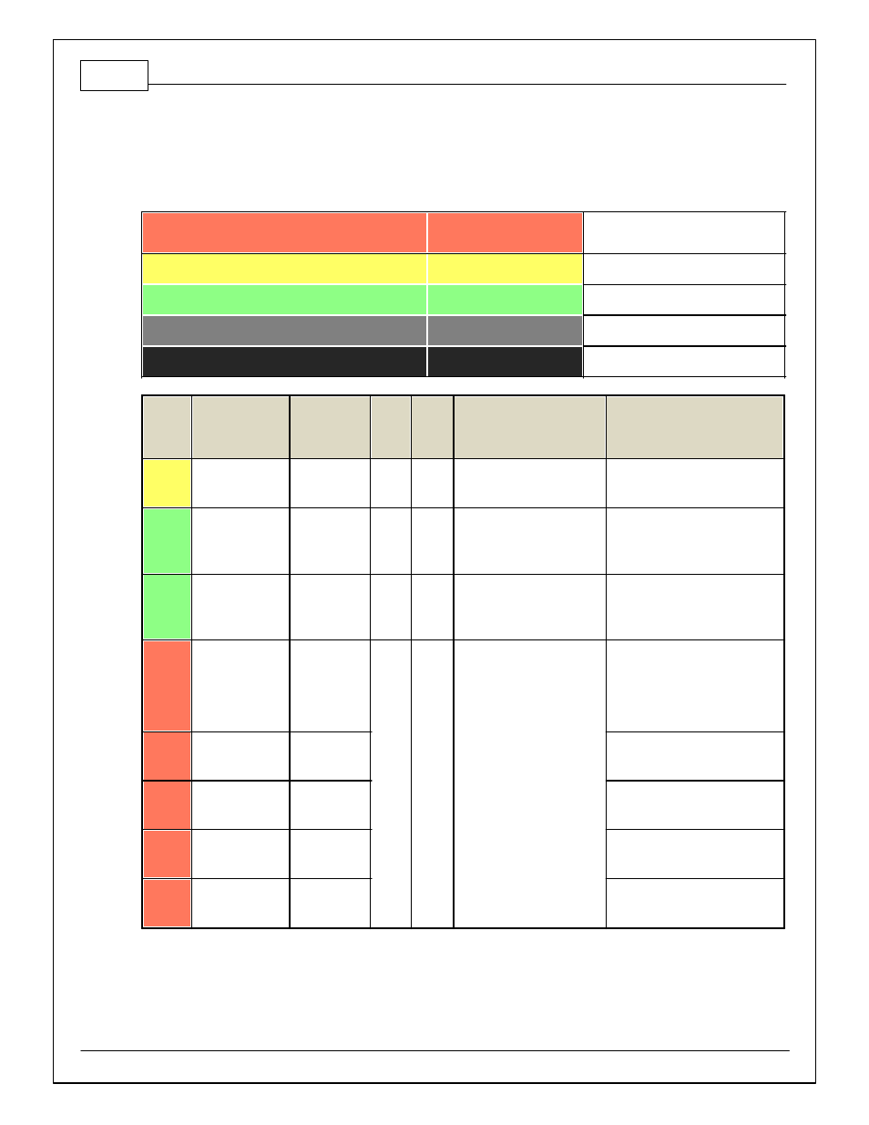
Dedicated
Dedicated and not
reconfigurable
Assigned
Assigned but reconfigurable
Available
Available for user setup
Not Applicable
Not used in this configuration
Required
Required for proper function
Infinity
Pin
Hardware
Reference
7100-XXXX-62
7101-XXXX-63
Function
Dest.
Pin
Evo
VIII
Dest.
Pin
Evo IX
Hardware Specification
Notes
C1-1
LowsideSwitch_4
A/C Relay
Control
8
20
Lowside switch, 4A max, NO
internal f ly back diode.
See "LowSide Assignment Tables" f or
output assignment.
C1-2
LowsideSwitch_5
LS5
21
18
Lowside switch, 4A max with
internal f ly back diode.
Inductiv e load should NOT
hav e f ull time power.
See Setup Wizard Page "LowSide
Assignment Tables" f or output
assignment and 2D table "LS5_Duty
[%]" f or activ ation.
C1-3
LowsideSwitch_6
LS6
Lowside switch, 4A max with
internal f ly back diode.
Inductiv e load should NOT
hav e f ull time power.
See Setup Wizard Page "LowSide
Assignment Tables" f or output
assignment and 2D table "LS6_Duty
[%]" f or activ ation.
C1-4
UEGO 1 Heat
UEGO 1 Heat
Bosch UEGO controller
Lowside switch f or UEGO heater
control. Connect to pin 4 of Bosch
UEGO sensor. NOTE that pin 3 of
the Sensor is heater (+) and must be
power by a f used/switched 12V
supply .
C1-5
UEGO 1 IA
UEGO 1 IA
Trim Current signal. Connect to pin 2
of Bosch UEGO sensor.
C1-6
UEGO 1 IP
UEGO 1 IP
Pumping Current signal. Connect to
pin 6 of Bosch UEGO sensor.
C1-7
UEGO 1 UN
UEGO 1 UN
Nernst Voltage signal. Connect to pin
1 of Bosch UEGO sensor.
C1-8
UEGO 1 VM
UEGO 1 VM
Virtual Ground signal. Connect to pin
5 of Bosch UEGO sensor.