AEM 30-1931 Universal Fuel Ignition Controller 8 Channel User Manual
Page 27
Page 27
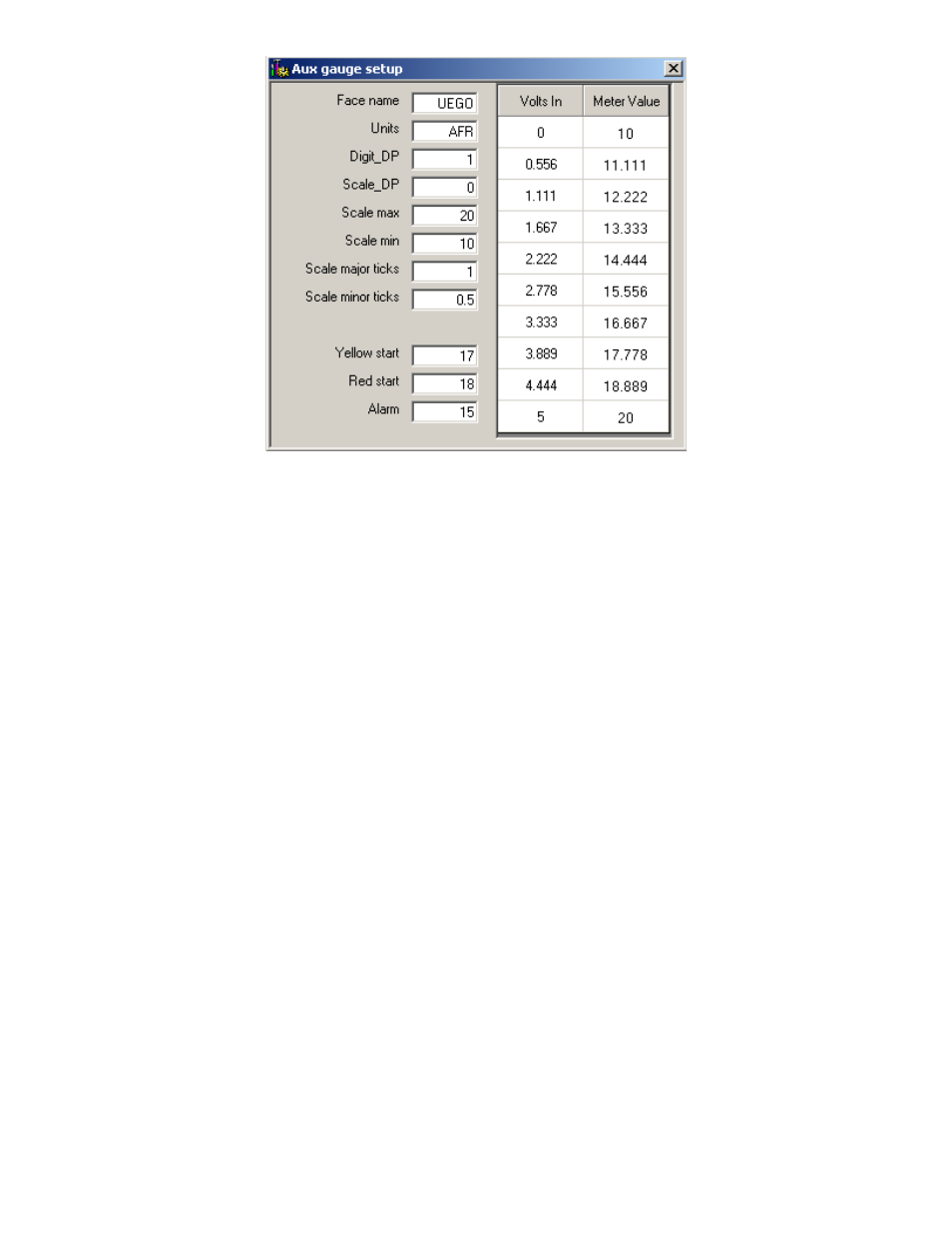
The Auxiliary gauge uses a 10 position calibration. Enter the input voltage value into
the
“Volts In” column. Enter the value to be displayed for each input voltage in the
corresponding row of the
“Meter Value” column. The appearance of the gauge is
configured by parameters on the left side of the
“Aux gauge setup” window. The Face
Name is displayed in bold letters just above the center of the gauge. The units are
displayed in smaller letters below the center of the gauge.
“Digit_DP” sets the number
of decimal places displayed by the large bold numbers at the bottom of the gauge.
“Scale_DP” sets the number of decimal places displayed by the tick mark values on the
gauge face.
“Scale max” and “Scale min” set the display range of the gauge. “Scale
major ticks
” and “Scale minor ticks” set the number of major and minor tick marks
displayed on the gauge.
“Yellow start” and “Red start” set the starting value for the
yellow and red regions of the gauge.
“Alarm” sets the value at which the gauge needle
starts flashing.
Analog C:
The analog C input channel is similar to the Auxiliary Gauge input and was
designed for use with an RTD type input, such as the AEM inlet air temp sensor (p/n 30-
2010). The Analog C input is internally tied to a user selectable 2.2kohm pull-up
resistor to 5 volts. When using an RTD type input, the 2.2K pull-up must be on. If
tapping an existing line or using a 0-5 volt sensor, the 2.2k pull-up is not necessary. In
order to view more meaningful data, the Analog C input voltage can be scaled to the
desired units using the “Analog C voltage table”, see Figure 37. When completing the
Analog C voltage table, the smallest voltage value must go in the top row of the volts in
column, while the largest voltage value goes in the bottom row. Enter the
corresponding scaled values into the Value column. The numbers in the Value column
are shown in the “Analog C Calc” box of the “Gauges” window.
Figure 36. Auxiliary Gauge Setup