AEM 30-1931 Universal Fuel Ignition Controller 8 Channel User Manual
Page 20
Page 20
Boost Map (See Figure 31)
The FIC8 has a pulse width modulated output that will drive the AEM boost
solenoid (P/N 30-2400) at varying duty cycles based on the Boost Map. The values
entered into the Boost Map are duty cycle values between 0 and 100%. The Boost Map
load input can be based on TPS, Analog C, or RPM. When RPM is selected, the Boost
Map has no load input. For a cell value of 30, the FIC outputs a signal at 30% duty
cycle. (Note: The solenoid output is 0% duty cycle for boost pressure less than 1psi
above atmospheric pressure.)
To aid in tuning, the FIC software has user configurable boost solenoid “Start
Pressure” and “Over-boost protection”. Both functions are configured in the “Boost”
section of the “Setup” window, see Figure 32. The FIC outputs a 100% duty cycle from
1psi above atmospheric pressure until the “Start Pressure” is reached. The FIC will
output the duty cycle values in the Boost Map for pressures greater than the “Start
Pressure” value. The “Start Pressure” value can be adjusted to minimize turbo lag.
Over-boost protection is enabled and disabled with the enable check box in the
“Over-boost protection” section of the “Setup” window, see Figure 32. The over-boost
conditions are also set in the “Over-boost protection” section.
The “Gauges” window contains an “Overboost” warning light and a boost valve
error (Boost valve ERR) light. The
“Overboost” light will illuminate when the overboost
conditions in the
“Setup” window have been met. The “Boost valve ERR“ light will
illuminate when the boost solenoid is disconnected or shorted.
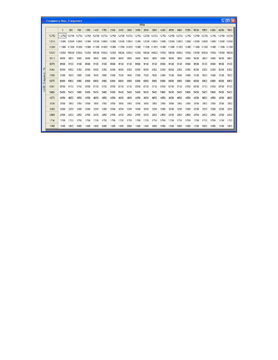
Figure 30. Frequency Map