Operation, Operati on – SkyTrak 10054 Operation Manual User Manual
Page 68
66
Model 10054
Rev 3/02
Operation
Understanding the Boom/Outrigger Interlock System
The ultimate purpose of this interlock system is to add an extra measure of
stability allowing the boom to be extended to its maximum limits. There are
two modes to this interlock, the Extend Interlock and the Outrigger Interlock.
Extend Interlock Mode
(Figure 42)
The Extend Interlock Mode (Figure 42), limits boom extension to a point
after letter "E" has appeared on the side of the boom and before letter "F"
appears (Figure 42). A sensor in the boom will automatically STOP the
boom from extending past this point until the outriggers have been lowered
onto firm terrain.
With the OUTRIGGERS RAISED (Figure 42) and the boom inside of the
extension limit the vehicle will function normally. The Stabil-TRAK system
should perform as designed.
Figure 42
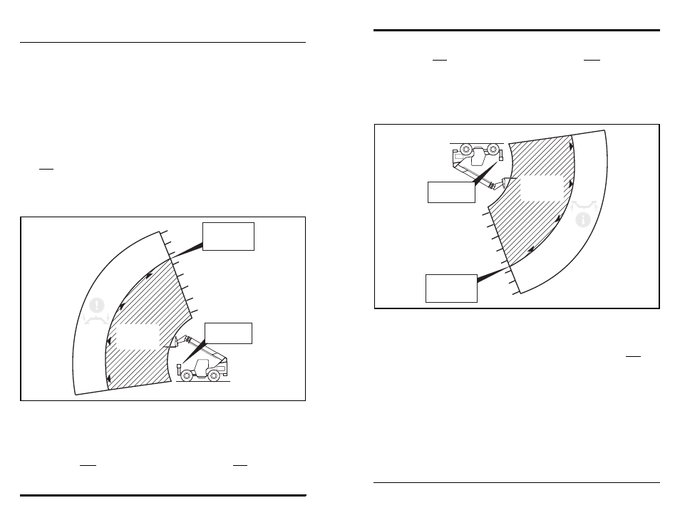
Outrigger Interlock Mode
(Figure 43)
The Outrigger Interlock Mode (Figure 43), allows for full boom extension
only as long as both outriggers have been lowered onto firm terrain (Figure
43) (OUTRIGGERS DOWN). Once this condition is met, the boom is
allowed to extend to its full limits.
H
G
F
E
D
C
B
A
OH0632
EXTEND
INTERLOCK
MODE
EXTEND
INTERLOCK
LIMIT
OUTRIGGERS
RAISED
66
Model
10054
Rev
3/02
Operati
on
Understan
ding
the
Boom/OutriggerInterl
ock
System
The
ultim
atepur
pose
of
thi
si
nter
loc
ks
ys
tem
is
to
add
an
ex
tra
meas
ure
of
stab
ility
allo
wing
theboo
mt
ob
ee
xte
ndedto
itsma
xim
um
lim
its.T
here
are
twom
odes
to
this
inte
rloc
k,
the
Exten
dIn
terloc
kand
the
Outr
igg
erInte
rlo
ck.
Exte
ndInterlock
Mode
(F
igur
e4
2)
The
Ex
te
ndI
nterloc
kMo
de(
Fig
ure
42)
,l
imi
ts
boom
ex
tens
ion
to
ap
oint
after
letter
"E
"h
asapp
eared
ont
hes
ide
of
the
boom
and
bef
ore
lette
r"
F"
appea
rs
(F
igur
e4
2).
Ase
nsor
inthe
boom
will
automa
tical
lyS
TO
Pthe
boom
from
ex
tendin
gp
ast
this
point
unti
lt
he
outr
igger
sha
ve
been
lo
wer
ed
onto
firm
terr
ain.
Wit
hthe
OUTRIG
GE
RSRA
ISED
(Fig
ure
42)
andthe
boom
ins
ideof
the
ex
tensio
nl
imit
thev
ehic
lewil
lfunc
tion
no
rm
ally
.T
heSta
bil-
TRAK
sys
tem
sh
ou
ldper
fo
rm
as
desig
ned.
Figure
42
OutriggerInt
erlockMode
(F
igur
e4
3)
The
Outr
igge
rI
nterloc
kMo
de(
Figur
e4
3),
allo
ws
for
full
boom
ex
tens
ion
only
asl
ongas
both
outr
igger
sha
ve
been
lo
wer
ed
onto
firm
te
rrain
(Fig
ure
43
)(
OU
TRIG
GE
RSDO
WN)
.O
nce
this
co
nditi
oni
smet,
theboo
mi
s
allo
wed
to
ex
ten
dt
oi
tsfu
llli
mits
.
H
G
F
E
D
C
B
A
OH06
32
EXT
EN
D
INTERLOCK
MODE
EXT
END
INT
ER
LO
CK
LIMIT
OUTR
IGGE
RS
RAISE
D