Oper ati on, Operation – SkyTrak 10054 Operation Manual User Manual
Page 35
Oper
ati
on
33
Model
10054
Rev
3/02
OutriggerC
ontrolS
witches
(F
igur
e1
4)
The
le
ft
and
right
outrigg
erco
ntrol
swi
tches
rai
seor
lower
the
cor
res
pondin
gou
trig
gers
.T
he
roc
ker
swi
tches
are
spr
ing
loade
dt
or
etur
nt
o
the
cent
er(
sto
p)pos
itio
nw
hen
rel
eased
.
Rais
eL
eftO
utr
igger
...........
.pr
ess
top
of
le
ft
sid
es
witc
h
Lo
we
rL
eft
Out
rigg
er....
.......
pre
ss
bo
ttom
of
le
fts
ides
witc
h
Rais
eR
igh
tO
utrigge
r.
.......
..p
re
ss
to
pof
rig
hts
ide
swi
tch
Lo
wer
Right
Outr
igger
........
..p
re
ss
bottom
ofr
ight
side
swi
tch
Figure
14
NOTE:Ou
trigg
erpos
itio
ni
sc
riti
cal
to
allo
wful
lex
tensio
no
ft
heboo
m.
Refer
to“
Under
stan
ding
the
Boom
/Outr
igger
Inter
lock
Sys
tem”on
page
66
for
ade
tailed
expl
anatio
nof
theint
erloc
k.
OH04
20
OH170
0
Right
Side
Ou
trigger
Switch
Left
Side
Ou
trigger
Switch
Operation
33
Model 10054
Rev 3/02
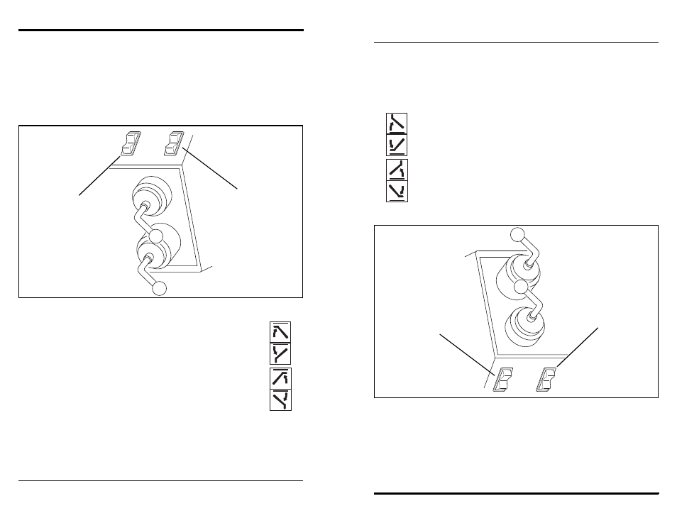
Outrigger Control Switches
(Figure 14)
The left and right outrigger control switches raise or lower the
corresponding outriggers. The rocker switches are spring loaded to return to
the center (stop) position when released.
Raise Left Outrigger............ press top of left side switch
Lower Left Outrigger ........... press bottom of left side switch
Raise Right Outrigger ..........press top of right side switch
Lower Right Outrigger..........press bottom of right side switch
Figure 14
NOTE: Outrigger position is critical to allow full extension of the boom.
Refer to “Understanding the Boom/Outrigger Interlock System” on page 66
for a detailed explanation of the interlock.
OH0420
OH1700
Right Side
Outrigger
Switch
Left Side
Outrigger
Switch