BNC 645 User Manual
Page 18
18
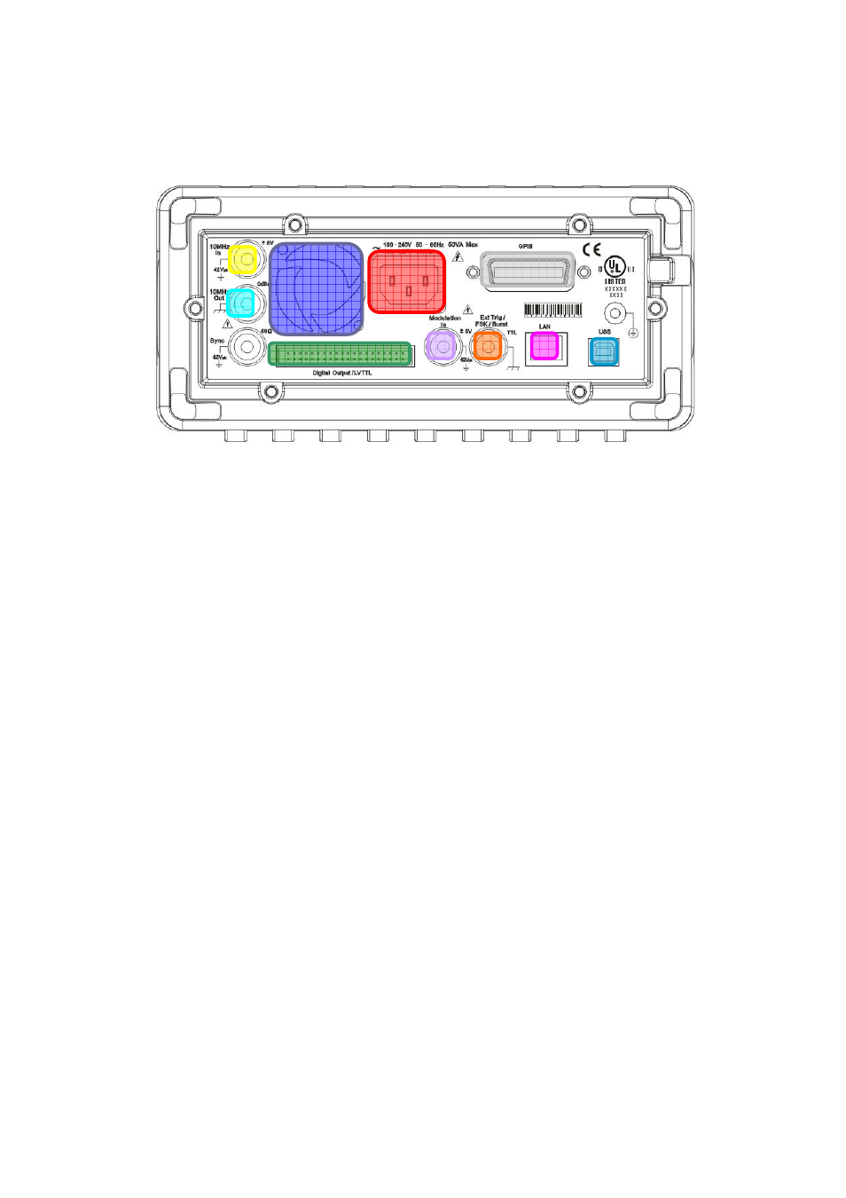
2.3.2 Rear Panel
Figure 2-7
1. 10MHz In (External 10 MHz Reference Input) Connector
2. 10MHz Out (Internal 10 MHz Reference Output) Connector
3. Modulation In (External Modulation Input) Connector
4. Trig In/Out, FSK/Burst Connector
5. LAN Port
6. GPIB Connector(Optional)
7. USB Port
8. Digital Pattern Output / LVTTL
9. Power cord Connector
10. Vent
1
2
3
4
6
8
7
9
10
5