BNC 725 User Manual
Page 22
22
-
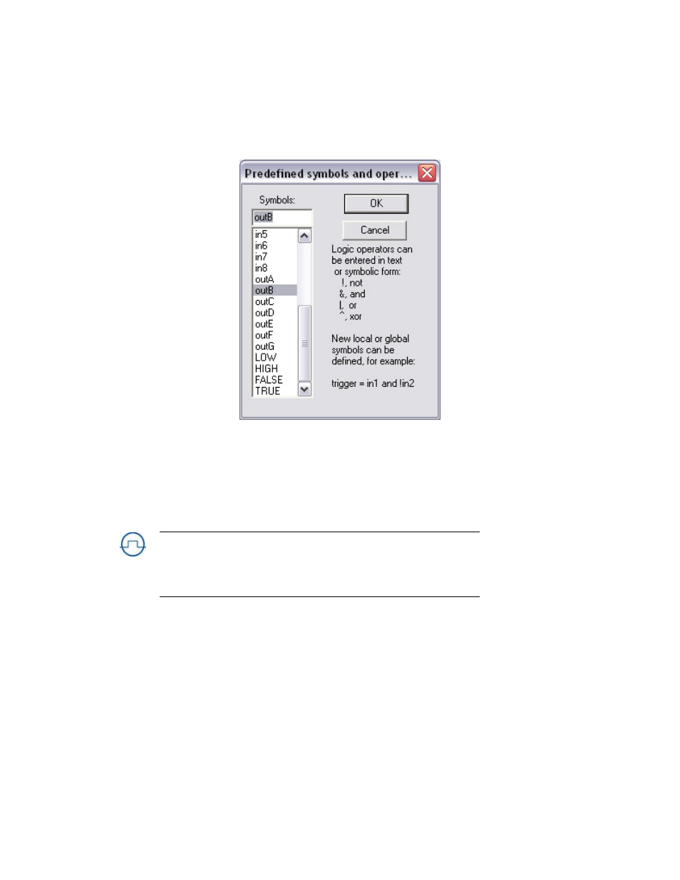
inA–inH: the input of channels A through H. These signals only appear internally at the
input of the timing channel; they are not connected to the rear BNCs. These symbols can
only be on the left-hand side of an assignment
-
in1–in8: inputs 1 through 8 from the rear BNC connectors.
-
outA–outG: outputs of channels A through G that appear at the rear BNC connectors.
NOTE:
The output of channel H is not internally connected to the logic processor. It
cannot be used in logic assignments unless it is externally connected to another channel
input.
-
LOW, FALSE: trigger input always low.
-
HIGH, TRUE: trigger input always high.
Double click a variable to copy it to your Logic assignment. You can also select the variable then
click OK.