Pre - assembly of wheel carrier, Pre - assembly of rear bar, Pre - assembly of the wheel carrier – ARB 5650010 User Manual
Page 8
PRE - ASSEMBLY OF REAR BAR
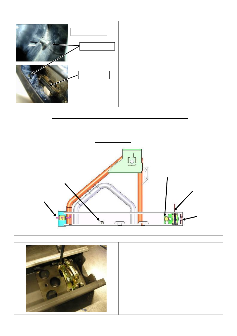
8. INSTALLATION OF PIVOT
ADJUSTING BOLT
Insert the M8 x 50 mm adjusting bolt (as
shown in the photo) through the hole in the
upright located in the right hand wing
cavity.
There is a corresponding tapped hole in the
pivot bracket that has been pre-drilled and
threaded. Wind the bolt in until a few
threads protrude through the bracket.
RH Wing Cavity
Adjusting Bolt
Pivot bracket
PRE - ASSEMBLY OF WHEEL CARRIER
THE FOLLOWING COMPONENTS CAN BE INSTALLED INTO THE WHEEL CARRIER BEFORE IT IS
FITTED TO THE REAR BAR .
NOTE :- THE BEARINGS AND SEALS ARE PRE - ASSEMBLED INTO THE WHEEL CARRIER BUSH TO AID
ASSEMBLY , THESE PARTS ARE LISTED IN THE PARTS LIST .
STOPPER
LOCKING PIN
STRUT SPHERE
CATCH ASSEMBLY
GRABBER
PRE - ASSEMBLY OF THE WHEEL CARRIER
1. INSTALLATION CATCH ASSEMBLY
Install the catch assembly using the four M8
x 20 mm socket head cap screws and spring
washers provided and fully tighten.
NOTE:- The mounting plate has been pre -
tapped to accept the socket head cap screws.
Last Rev Date: 16/10/2006
Page 8 of 25
3783210 - rev 3
Copyright © 2005 by ARB Corporation Limited. All rights reserved, this document must not be reproduced without the express authority of ARB Corporation Ltd