Adjustment of the rear step components, Final check and adjustment on the wheel carrier, Fitting the wheel mounting bracket – ARB 5650010 User Manual
Page 19
ADJUSTMENT OF THE REAR STEP COMPONENTS
12. ADJUSTING THE GRABBER BRACKET
With the bolts attaching the catch grabber bracket finger tight, shut the wheel carrier. This will
centralise the grabber bracket.
Taking care not to knock the grabber bracket, release the catch and swing the wheel carrier out into
the open position.
Tighten the bolts securing the grabber bracket to the rear bar.
FINAL CHECK AND ADJUSTMENT ON THE WHEEL CARRIER
With all of the bolts now tightened, shut the wheel carrier until the catch locks. The arm should
meet little resistance as it shuts and the catch should make a crisp ‘click’ sound as it closes.
At this point, it should not be possible to pull the wheel carrier open without releasing the catch.
There should be no free play between the wheel carrier and the rear bar.
Stand behind the vehicle and pull the catch lever. The catch should make a crisp ‘click’ sound and
the arm should open without further assistance.
IMPORTANT: - IF THE ARM DOES NOT OPERATE IN THIS
MANNER REPEAT STEPS 10 TO 13.
FITTING THE WHEEL MOUNTING BRACKET
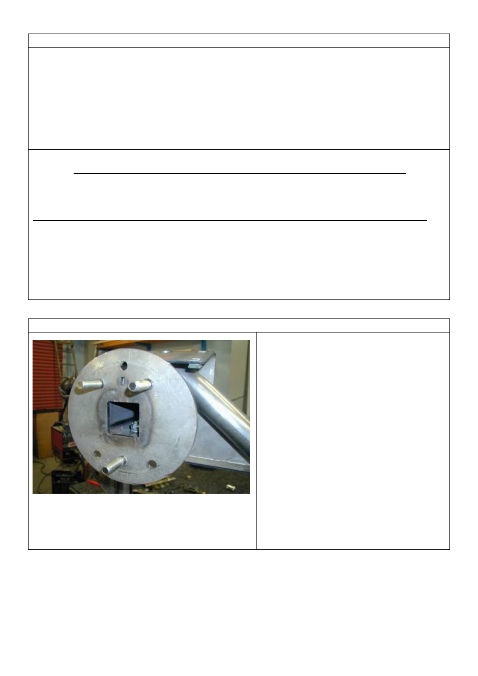
Studs positioned in the 5 x 4 ½” pattern.
Vacant holes are used for 5 x 5 ½” pattern
1.
STUD LOCATIONS ON THE
WHEEL MOUNT BRACKET
Studs can be fitted to the wheel mount
bracket in either a 5 x 4 ½” or 5 x 5 ½”
pattern.
The photo to the right shows the studs
in the 5 x 4 ½” pattern.
The studs are installed in the vacant
holes to achieve the 5 x 5 ½” pattern.
Installation of the studs is covered in
step 2.
Last Rev Date: 16/10/2006
Page 19 of 25
3783210 - rev 3
Copyright © 2005 by ARB Corporation Limited. All rights reserved, this document must not be reproduced without the express authority of ARB Corporation Ltd