Lenovo Secure Managed Client User Manual
Page 82
20.
Install
the
memory
FBDIMMs.
For
instructions,
see
“Installing
FBDIMMs”
on
page
45.
21.
Reconnect
all
the
cables
disconnected
in
Step
22.
Install
standoff
4 .
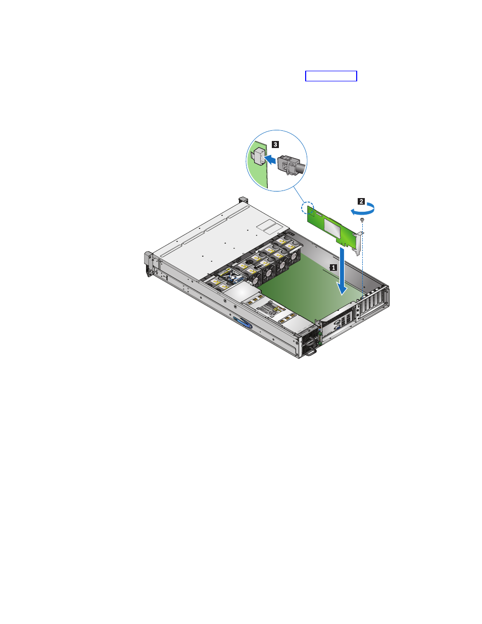
23.
Install
the
Intel
RAID
Controller
SRCSATAWB
in
the
3rd
PCI
slot
from
the
right
1 .
Tighten
the
screw
2
on
the
retaining
bracket
at
the
back
of
the
enclosure.
Connect
the
SAS
cable
3 .
24.
If
used,
install
the
SATA
or
USB
DOM.
25.
This
step
is
for
SATA
DOM
only.
Connect
the
P4
power
cable
to
the
power
adapter
for
the
SATA
DOM.
26.
If
the
boot
drive
was
disconnected,
connect
the
P4
power
cable
to
the
boot
drive
module
backplane.
Note:
The
P4
power
cable
is
connected
to
the
boot
drive
module
backplane
when
using
boot
drives.
If
using
a
SATA
DOM,
the
P4
power
cable
is
connected
to
the
power
adapter
of
the
SATA
DOM
device.
Power
for
a
USB
DOM
device
is
provided
by
the
USB
connector.
27.
If
the
boot
drive
was
disconnected,
connect
the
two
SAS/SATA
cables
to
the
boot
drive
module
backplane.
28.
Reinstall
the
boot
drive
module
in
the
enclosure,
securing
it
in
place
with
the
screw
removed
previously.
76
Hardware
Maintenance
Manual