Drive status indicator, Anti-tamper locks, Removing and installing a processor – Lenovo Secure Managed Client User Manual
Page 71: Drive, Status, Indicator, Anti-tamper, Locks, Removing, Installing
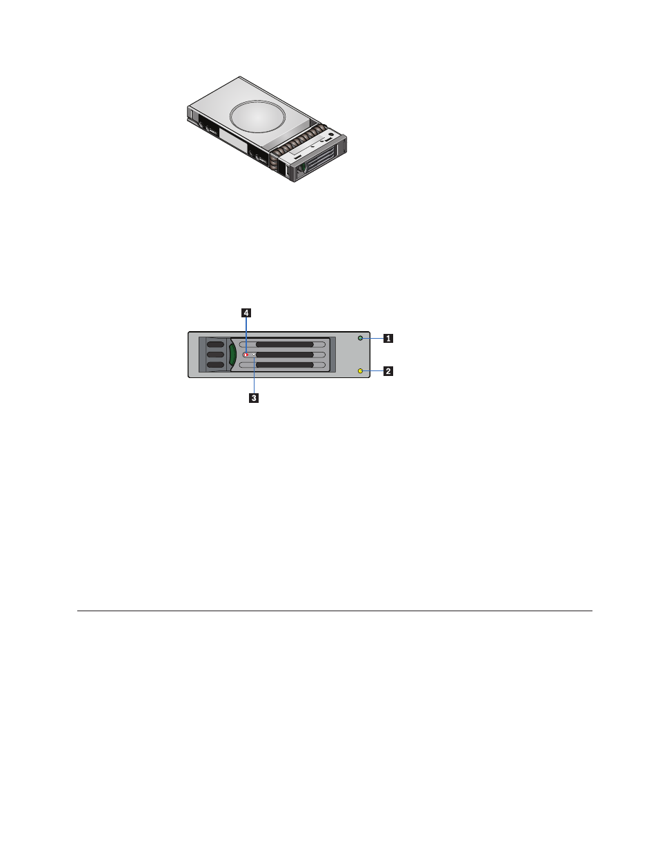
Drive
status
indicator
Disk
drive
status,
under
ESI
processor
control,
is
monitored
by
two
LEDs
(a
green
LED
and
an
amber
LED)
mounted
on
the
front
cap
of
each
drive
carrier
module.
1 Green
LED
2 Amber
LED
3 Torque
screw
4 Drive
lock
indicator
opening
Anti-tamper
locks
Anti-tamper
locks
are
installed
in
each
drive
carrier
handle
and
are
accessed
with
a
TORX
screwdriver
through
the
small
cutout
in
the
latch
section
of
the
handle.
When
activated,
the
locks
disable
the
normal
"pinch"
latch
action
of
the
drive
carrier
handle.
A
drive
is
locked
when
the
red
lock
symbol
appears
in
the
indicator
opening.
Removing
and
installing
a
processor
To
install
a
processor,
complete
the
steps
in
this
section.
CAUTION:
Reduce
the
risk
of
ESD
damage
to
the
processor
by
doing
the
following:
v
Touch
the
metal
chassis
before
touching
the
processor
or
server
board.
Keep
part
of
your
body
in
contact
with
the
metal
chassis
to
dissipate
the
static
charge
while
handling
the
processor.
v
Avoid
moving
around
unnecessarily.
Figure
12.
Driver
carrier
module
Figure
13.
Drive
status
LEDs
and
components
Chapter
8.
Features
65