Server board i/o panel, Connectors, Server board leds – Lenovo Secure Managed Client User Manual
Page 67: Front operators panel, Server, Board, Panel, Front, Operator's, Leds
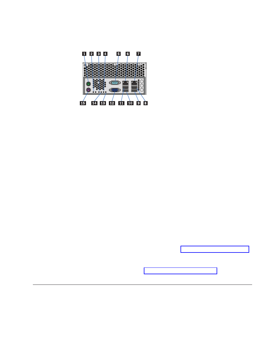
Server
board
I/O
panel
The
server
board
I/O
panel
consists
of
various
connectors
and
LEDs.
1 PS2
mouse
port
9 Bit
2
(POST
LED)
2 System
status
LED
10 LSB
(POST
LED)
3 MSB
(POST
LED)
11 Video
port
4 Bit
1
(POST
LED)
12 USB
port
2
5 Serial
port
13 USB
port
3
6 NIC
port
1
(1
Gb)
14 USB
port
1
7 NIC
port
2
(1
Gb)
15 USB
port
0
8 PS2
keyboard
Connectors
The
following
connectors
are
located
on
the
server
board
I/O
panel:
v
PS2
mouse
port
v
PS2
keyboard
port
v
Serial
port
v
Video
port
v
Two
RJ-45
ports
-
NICs
1
and
2
(1Gb
each)
v
Four
USB
ports:
0,
1,
2,
and
3
Server
board
LEDs
Status
LEDs:
Diagnostic
LEDs
are
located
on
the
server
board
I/O
panel
to
assist
in
identifying
failed
and
failing
components.
See
for
a
summary
of
status
LED
states.
NIC
LEDs:
The
NIC
LEDs
at
the
right
and
left
of
each
NIC
port
provide
information
on
NIC
status.
See
for
a
summary
of
NIC
LED
states.
Front
operator's
panel
A
front
operator’s
panel,
consisting
of
a
USB
port,
three
LEDs
and
three
push-button
switches,
are
located
on
the
front
of
the
enclosure.
Note:
The
front
operator’s
panel
is
an
integral
part
of
the
enclosure
assembly
and
is
not
field
replaceable.
Figure
8.
Server
board
I/O
panel
connectors
Chapter
8.
Features
61