Lenovo Secure Managed Client User Manual
Page 81
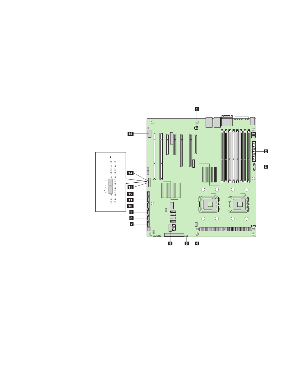
15.
Disconnect
the
following
cables:
v
P12V4
cable
1
v
Main
power
cable
2
v
Auxiliary
power
signal
cable
3
v
IPBM
cable
5
v
(Disregard
if
using
a
USB
DOM)
USB
header
6
v
All
SAS
and/or
SATA
cables
7
thru
12
v
Front
control
panel
cables
13
and
14
v
Serial
B/emergency
management
port
cable
15
16.
16.
Remove
standoff
4 .
Power
Reset
1
P12V4
cable
connector
9
SATA
2
or
SAS
0
cable
connector
2
Main
power
cable
connector
10
SATA
3
or
SAS
1
cable
connector
3
Auxiliary
power
signal
cable
connector
11
SATA
4
or
SAS
2
cable
connector
4
Standoff
12
SAS
or
SATA
cable
connector
5
IPBM
cable
connector
13
Front
control
panel
cable
connector
6
USB
cable
connector
14
Front
control
panel
cable
connector
7
SATA
0
cable
connector
15
Serial
B/emergency
management
port
cable
connector
8
SATA
1
cable
connector
17.
Remove
the
seven
screws
securing
the
server
board
to
the
chassis.
Remove
server
board
from
chassis
and
place
in
an
anti-static
bag.
18.
Install
the
new
server
board
by
aligning
the
screw
holes
in
the
server
board
with
the
standoffs
in
the
chassis.
19.
Install
the
processor(s)
and
heatsink(s).
For
instructions,
see
“Installing
the
Processor”
on
page
49.
Chapter
8.
Features
75