Nugget 500 series valves, Val-11-17 – Norgren 500 Series Nugget User Manual
Page 17
Littleton, CO USA
Phone: 303-794-2611
www.norgren.com
VAL-11-17
Nugget 500 Series Valves
For ordering information, the valve and
manifolding subbase assembly are oriented
with the 1 2 operator end on the left side,
and the 1 4 operator end on the right side.
The valves are listed from FRONT to BACK.
This example illustrates how to order a valve
and manifolding subbase assembly, with
isolating plugs for two different working
pressures installed between valve manifold
subbases 2 and 3.
Four pipe plugs are included with the end
plate kit to allow blocking of unused common
inlet, exhaust, and pilot end plate ports to
prevent air loss and entry of contaminants.
Valve
Pos.
Product
Special
No.
Qty.
Number
Instructions
1
1
MN01GCA-75-ALJA
2
1
MN01GGA-75-ALJA
1
54676-50
Install
isolating
plugs
3
1
MN01GGA-75-ALJA
4
1
MN01GGA-75-ALJA
1
13338-50
End Plate kit
4
99-059-530
Ass’y charge
Factory Assembled Valve and Manifolding Subbase Assemblies
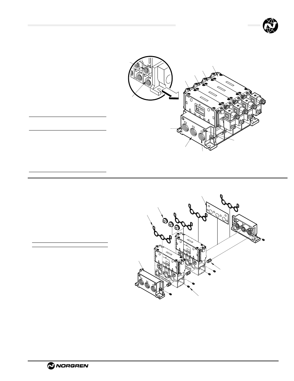
Isolating Plug Kits
An isolating plug kit is available to allow the
use of different inlet pressures. A valve and
manifolding subbase assembly can be
divided into two sections by inserting
isolating plugs between any two manifolding
subbases.
The drawing at right illustrates a valve and
manifolding subbase assembly separated
for a two pressure applications by isolating
plugs.
Ordering Information
Isolating Plug Kit*
54676-50
*Kit contains 3-Isolating Plugs
Port 2
3/8" or 1/2"
Cylinder Ports
Port 4
3/8" or 1/2"
Cylinder Ports
Set Screw
End Plate
Seal
Isolating Plugs
Separator
Clamping Pin
Valve 1
Valve 2
Valve 3
Valve 4
Port 3
3/4" Common
Exhaust Port
Port 1
3/4" Common
Inlet Port
Port 5
3/4" Common
Exhaust Port
1/8 External
Pilot Supply Port
FRONT
BACK
1 2 END
1 4 END