Digital characteristics, Analog specifications – Cirrus Logic CS61583 User Manual
Page 4
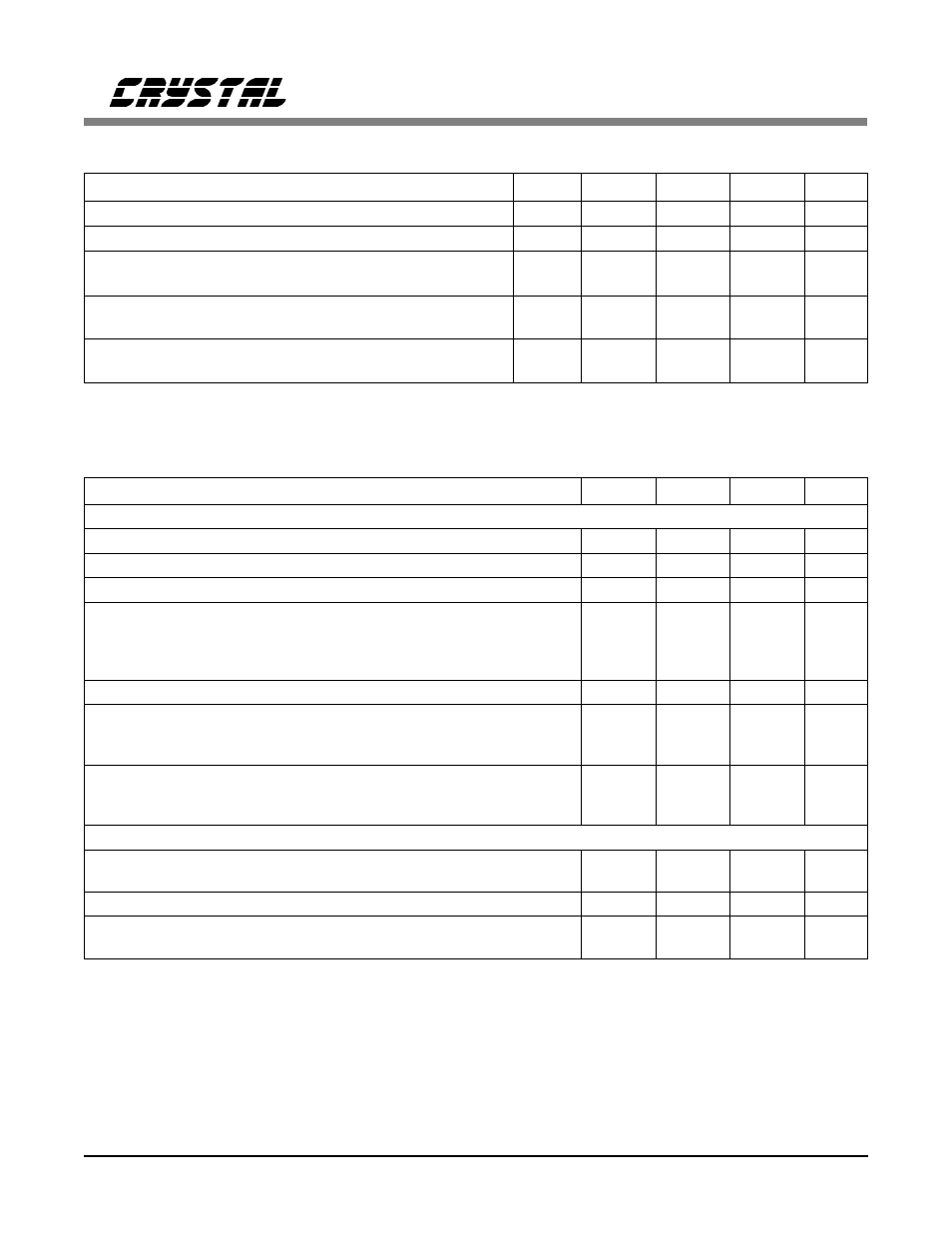
DIGITAL CHARACTERISTICS
(T
A
= -40 to 85 °C; power supply pins within
±
5% of nominal)
Parameter
Symbol
Min
Typ
Max
Units
High-Level Input Voltage
(Note 7)
V
IH
(DV+)-0.5
-
-
V
Low-Level Input Voltage
(Note 7)
V
IL
-
-
0.5
V
High-Level Output Voltage
(Note 8)
(Digital pins)
IOUT = -40
µ
A
V
OH
(DV+)-0.3
-
-
V
Low-Level Output Voltage
(Note 8)
(Digital pins)
IOUT = 1.6 mA
V
OL
-
-
0.3
V
Input Leakage Current
(Digital pins except J-TMS, and J-TDI)
-
-
±
10
µ
A
Notes:
7. Digital inputs are designed for CMOS logic levels.
8. Digital outputs are TTL compatible and drive CMOS levels into a CMOS load.
ANALOG SPECIFICATIONS
(T
A
= -40 to 85 °C; power supply pins within
±
5% of nominal)
Parameter
Min
Typ
Max
Units
Receiver
RTIP/RRING Differential Input Impedance
-
20k
-
Ω
Sensitivity Below DSX-1 (0 dB = 2.4 V)
-13.6
-
-
dB
Loss of Signal Threshold
-
0.3
-
V
Data Decision Threshold
T1, DSX-1
(Note 9)
(Note 10)
E1
(Note 11)
(Note 12)
60
55
45
40
65
-
50
-
70
75
55
60
% of
Peak
Allowable Consecutive Zeros before LOS
160
175
190
bits
Receiver Input Jitter
10 Hz and below
(Note 13)
Tolerance (DSX-1, E1)
2 kHz
10 kHz - 100 kHz
300
6.0
0.4
-
-
-
-
-
-
UI
UI
UI
Receiver Return Loss
51 kHz - 102 kHz
(Notes 14,
102 kHz - 2.048 MHz
21, and 22)
2.048 MHz - 3.072 MHz
12
18
14
-
-
-
-
-
-
dB
dB
dB
Jitter Attenuator
Jitter Attenuation Curve
T1
(Notes 14 and 15)
Corner Frequency
E1
-
-
4
5.5
-
-
Hz
Hz
Attenuation at 10 kHz Jitter Frequency
(Notes 14 and 15)
-
60
-
dB
Attenuator Input Jitter Tolerance
(Note 14)
(Before Onset of FIFO Overflow or Underflow Protection)
28
43
-
UI
pk-pk
Notes:
9. For input amplitude of 1.2 V
pk
to 4.14 V
pk
10. For input amplitude of 0.5 V
pk
to 1.2 V
pk
, and 4.14 V
pk
to 5.0 V
pk
11. For input amplitude of 1.07 V
pk
to 4.14 V
pk
,
12. For input amplitude of 4.14 V
pk
to 5.0 V
pk
,
13. Jitter tolerance increases at lower frequencies. Refer to the Receiver section.
14. Not production tested. Parameters guaranteed by design and characterization.
15. Attenuation measured with sinusoidal input jitter equal to 3/4 of measured jitter tolerance.
Circuit attenuates jitter at 20 dB/decade above the corner frequency. Output jitter
can increase significantly when more than 28 UI’s are input to the attenuator. Refer to the
Jitter Attenuator section.
CS61583
4
DS172PP5