Cirrus Logic CS61583 User Manual
Page 11
during the transmission of both marks and
spaces. This improves signal quality by minimiz-
ing reflections from the transmitter. Impedance
matching also reduces load power consumption
by a factor of two when compared to the return
loss achieved by using external resistors.
The CS61583 driver will automatically detect an
inactive TLCK input (i.e., no valid data is being
clocked to the driver). When this condition is de-
tected, the driver is forced low (except during
remote loopback) to output spaces and prevent
TTIP and TRING from entering a constant trans-
mit-mark state.
When any transmit configuration established by
CON[2:0], TAOS, or LLOOP changed states, the
transmitter stabilizes within 22 TCLK bit peri-
ods. The transmitter takes longer to stabilize
when RLOOP1 or RLOOP2 is selected because
the timing circuitry must adjust to the new fre-
quency from RCLK.
When the transmitter transformer secondaries are
shorted through a 0.5 ohm resistor, the transmit-
500
1.0
0.5
0
-0.5
0
250
750
1000
NORMALIZED
AMPLITUDE
CS61583
OUTPUT
PULSE SHAPE
TIME (nanoseconds)
ANSI T1.102
SPECIFICATION
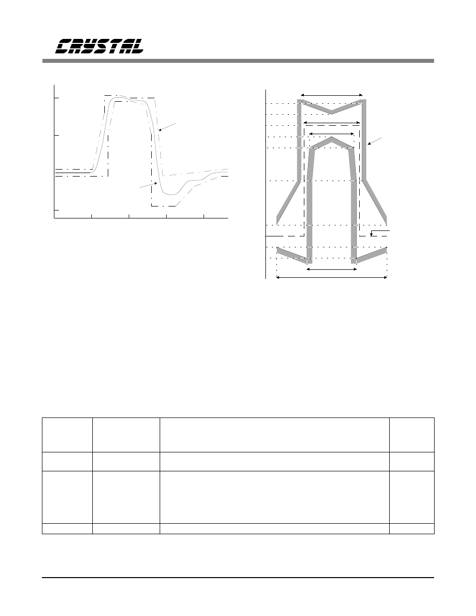
Figure 6. Typical Pulse Shape at DSX-1 Cross Connect
269 ns
244 ns
194 ns
219 ns
488 ns
Nominal Pulse
0
10
50
80
90
100
110
120
-10
-20
Percent of
nominal
peak
voltage
G.703
Specification
Figure 7. Pulse Mask at the 2048 kbps Interface
C
O
N
2
C
O
N
1
C
O
N
0
Transmit Pulse
Width at 50%
Amplitude
Transmit Pulse Shape
Receiver
Slicing
Level
0
0
0
0
0
1
244 ns (50%)
244 ns (50%)
E1: square, 2.37 Volts into 75
Ω
E1: square, 3.00 Volts into 120
Ω
50%
50%
0
1
0
350 ns (54%)
DSX-1: 0-133 ft. / or DS1 FCC Part 68 Option A with undershoot
65%
0
1
1
350 ns (54%)
DSX-1: 133-266 ft.
65%
1
0
0
350 ns (54%)
DSX-1: 266-399 ft.
65%
1
0
1
350 ns (54%)
DSX-1: 399-533 ft.
65%
1
1
0
350 ns (54%)
DSX-1: 533-655 ft.
65%
1
1
1
324 ns (50%)
DS1: FCC Part 68 Option A (0 dB)
65%
Table 1. Configuration Selection
CS61583
DS172PP5
11