Absolute maximum ratings, Recommended operating conditions – Cirrus Logic CS61583 User Manual
Page 3
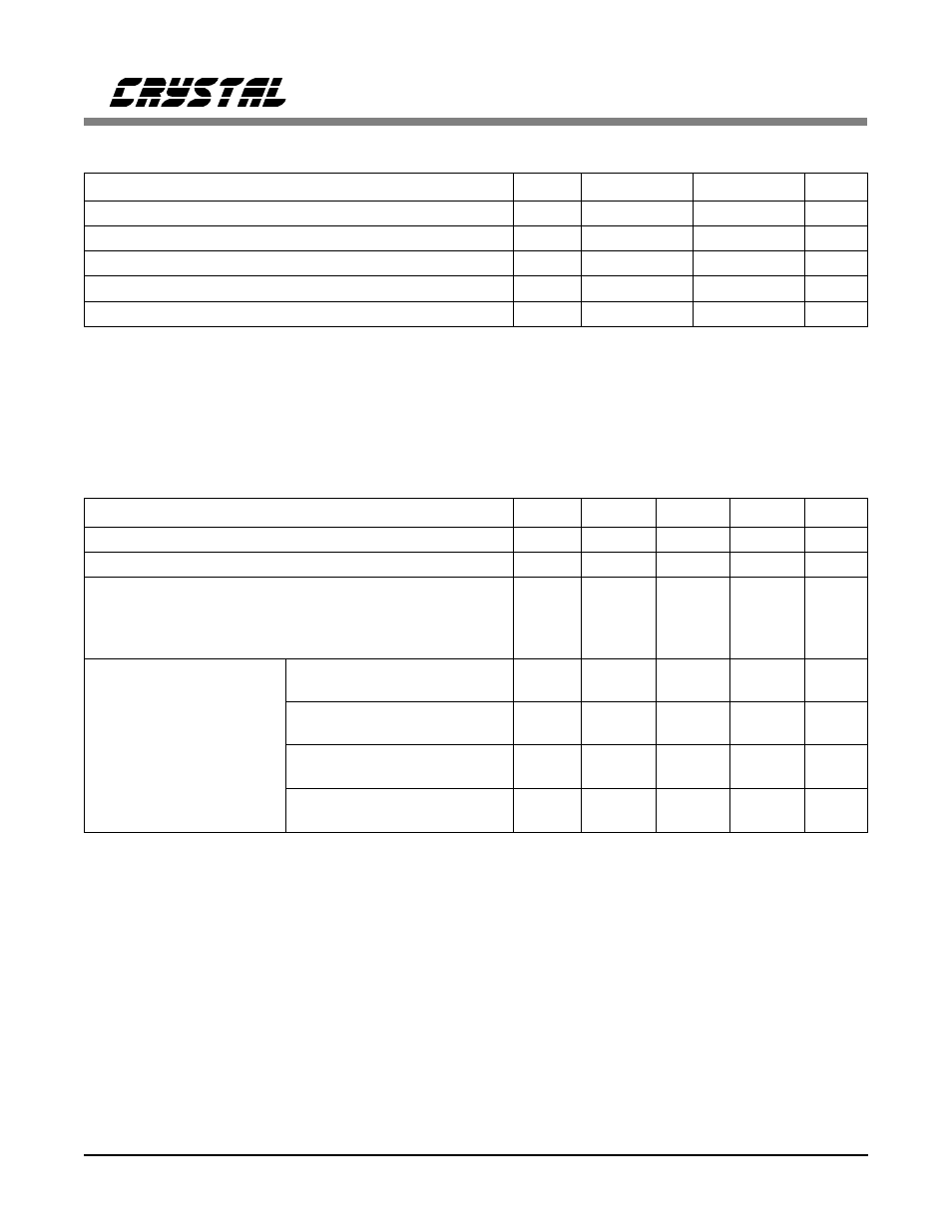
ABSOLUTE MAXIMUM RATINGS
Parameter
Symbol
Min
Max
Units
DC Supply (TV+1, TV+2, RV+1, RV+2, AV+, DV+) (Note 1)
-
6.0
V
Input Voltage (Any Pin)
V
in
RGND - 0.3
(RV+) + 0.3
V
Input Current (Any Pin)
(Note 2)
I
in
-10
10
mA
Ambient Operating Temperature
T
A
-40
85
°C
Storage Temperature
T
stg
-65
150
°C
WARNING: Operations at or beyond these limits may result in permanent damage to the device.
Normal operation is not guaranteed at these extremes.
Notes:
1. Referenced to RGND1, RGND2, TGND1, TGND2, AGND, DGND at 0V.
2. Transient currents of up to 100 mA will not cause SCR latch-up.
RECOMMENDED OPERATING CONDITIONS
Parameter
Symbol
Min
Typ
Max
Units
DC Supply (TV+1, TV+2, RV+1, RV+2, AV+, DV+) (Note 3)
4.75
5.0
5.25
V
Ambient Operating Temperature
T
A
-40
25
85
°C
Power Consumption
T1
(Notes 4 and 5)
(Each Channel)
T1
(Notes 4 and 6)
E1, 75
Ω
(Notes 4 and 5)
E1, 120
Ω
(Notes 4 and 5)
P
C
-
-
-
-
310
220
275
275
-
-
-
-
mW
mW
mW
mW
REFCLK Frequency
T1
1XCLK = 1
1.544 -
100 ppm
1.544
1.544 +
100 ppm
MHz
T1
1XCLK = 0
12.352 -
100 ppm
12.352
12.352 +
100 ppm
MHz
E1
1XCLK = 1
2.048 -
100 ppm
2.048
2.048 +
100 ppm
MHz
E1
1XCLK = 0
16.384 -
100 ppm
16.384
16.384 +
100 ppm
MHz
Notes:
3. TV+1, TV+2, AV+, DV+, RV+1, RV+2 should be connected together. TGND1, TGND2, RGND1,
RGND2, DGND1, DGND2, DGND3 should be connected together.
4. Power consumption while driving line load over operating temperature range. Includes IC and load.
Digital input levels are within 10% of the supply rails and digital outputs are driving a 50 pF
capacitive load.
5. Assumes 100% ones density and maximum line length at 5.25V.
6. Assumes 50% ones density and 300ft. line length at 5.0V.
CS61583
DS172PP5
3