Cirrus Logic CS61583 User Manual
Page 34
Features
••
Socketed CS61583 Dual Line Interface
••
All Required Components for CS61583
Evaluation
••
Locations to Evaluate Protection Circuitry
••
LED Status Indications for Alarm
Conditions
••
Control of Enhanced Hardware Options
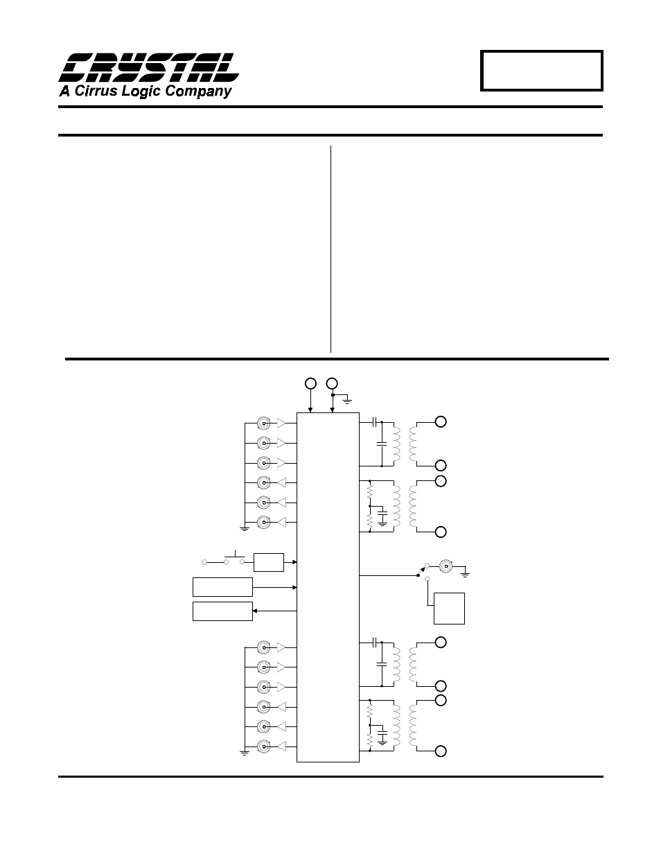
General Description
The evaluation board includes a socketed CS61583
dual line interface device and all support components
necessary for evaluation. The board is powered by
an external +5 Volt supply.
The board may be configured for 100
Ω
twisted-pair
T1, 75
Ω
coax E1, or 120
Ω
twisted-pair E1 operation.
Binding posts and bantam jacks are provided for line
interface connections. Several BNC connectors pro-
vide clock and data I/O at the system interface.
Reference timing may be derived from a crystal oscil-
lator or an external reference clock. Four LED
indicators monitor device alarm conditions.
ORDERING INFORMATION: CDB61583
DEC ’95
DB172PP1
34
Crystal Semiconductor Corporation
P.O. Box 17847, Austin, TX 78760
(512) 445-7222 FAX: (512) 445 7581
Dual Line Interface Evaluation Board
CDB61583
Copyright
Crystal Semiconductor Corporation 1995
(All Rights Reserved)
Oscillator
Circuit
TTIP1
TRING1
RTIP1
RRING1
TTIP2
TRING2
RTIP2
RRING2
}
CHANNEL 1
}
CHANNEL 2
+5V
0V
TCLK1
TPOS1
(TDATA1)
TNEG1
RCLK1
RPOS1
(RDATA1)
RNEG1
(BPV1)
{
CHANNEL 1
RESET
CIRCUIT
+5V
TCLK2
TPOS2
(TDATA2)
TNEG2
RCLK2
RPOS2
(RDATA2)
RNEG2
(BPV2)
CHANNEL 2
Hardware Control
and Mode Circuit
LED Status
Indicators
{
CS61583
REFCLK