Cirrus Logic CS61583 User Manual
Page 32
resistor must be connected from BGREF to
ground to provide an internal current reference.
De-coupling and filtering of the power supplies is
crucial for the proper operation of the analog cir-
cuits. A capacitor should be connected between
each supply and its respective ground. For capaci-
tors smaller than 1
µ
F, use mylar or ceramic
capacitors and place them as close as possible to
their respective power supply pins. Wire-wrap
bread boarding of the line interface is not recom-
mended because lead resistance and inductance
defeat the function of the de-coupling capacitors.
Crystal Oscillator Specifications
When a reference clock signal is not available, a
CMOS crystal oscillator operating at either the
1X or 8X rate can be connected at the REFCLK
pin. The oscillator must have a minimum symme-
try of 40-60% and minimum stability of
±
100
ppm for T1 and E1 applications. Based on these
specifications, some suggested crystal oscillators
for use with the CS61583 are shown in Table A2.
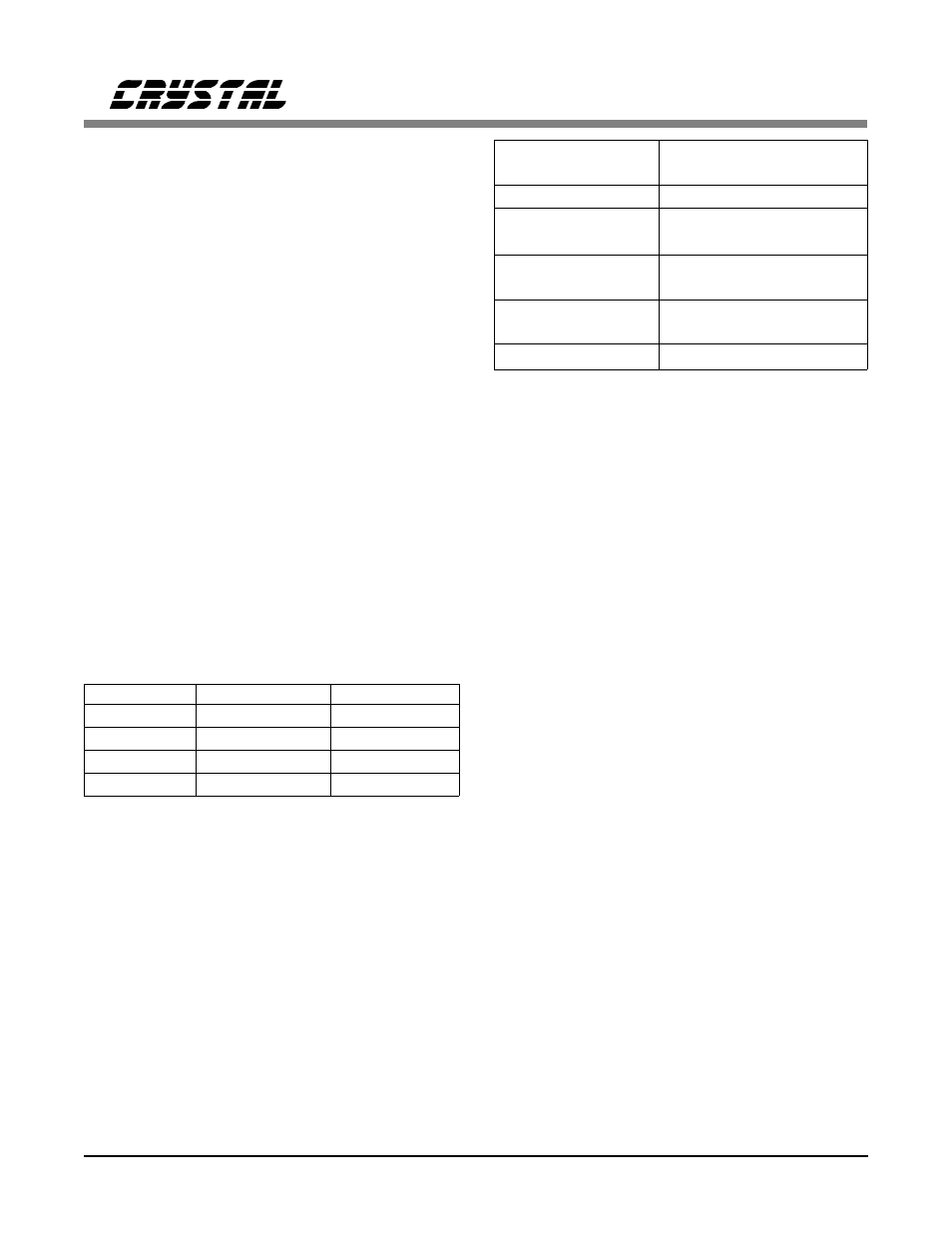
Transformers
Recommended transformer specifications are
shown in Table A3. Based on these specifications,
the transformers recommended for use with the
CS61583 are listed in Table A4.
Designing for AT&T 62411
For additional information on the requirements of
AT&T 62411 and the design of an appropriate
system synchronizer, refer to the Crystal Semi-
conductor Application Notes "AT&T 62411
Design Considerations - Jitter and Synchroniza-
tio n" a nd " Ji t ter Test ing Proce dure s f o r
Compliance with AT&T 62411."
Line Protection
Secondary protection components can be added
to the line interface circuitry to provide lightning
surge and AC power-cross immunity. For addi-
tional information on the different electrical
safety standards and specific application circuit
recommendations, refer to the Crystal Semicon-
ductor Application Note "Secondary Line
Protection for T1 and E1 Line Cards."
Turns Ratio
1:1.15 step-up transmit
1:1.15 step-down receive
Primary inductance
1.5 mH min at 772 kHz
Primary leakage
inductance
0.3
µ
H max at 772 kHz
with secondary shorted
Secondary leakage
inductance
0.4
µ
H max at 772 kHz
Interwinding
capacitance
18 pF max, primary to
secondary
ET-constant
16 V-
µ
s min
Table A3. Transformer Specifications
Manufacturer
Part Number
Contact Number
Comclok
CT31CH
(800) 333-9825
CTS
CXO-65HG-5-I (815) 786-8411
M-tron
MH26TAD
(800) 762-8800
SaRonix
NTH250A
(800) 227-8974
Notes:
Frequency tolerances are
±
32 ppm with a -40 to +85 °C
operating temperature range.
All are 8-pin DIP packages and can be tristated.
Table A2. Suggested Crystal Oscillators
CS61583
32
DS172PP5