1 cirrus logic 32-bit dsp core, 2 dsp memory, 1 dma controller – Cirrus Logic CS470xx User Manual
Page 9: 3 on-chip dsp peripherals, 1 analog to digital converter port (adc)
9
DS787PP9
4.1 Cirrus Logic 32-bit DSP Core
4.1 Cirrus Logic 32-bit DSP Core
The CS470xx comes with a Cirrus Logic 32-bit core with separate X and Y data and P code memory spaces. The DSP
core is a high-performance, 32-bit, user-programmable, fixed-point DSP that is capable of performing two
multiply-and-accumulate (MAC) operations per clock cycle. The DSP core has eight 72-bit accumulators, four X-data and
four Y-data registers, and 12 index registers.
The DSP core is coupled to a flexible 8-channel DMA engine. The DMA engine can move data between peripherals such
as the serial control port (SCP), digital audio input (DAI) and digital audio output (DAO), sample rate converters (SRC),
analog-to-digital converters (ADC), digital-to-analog converters (DAC), or any DSP core memory, all without the
intervention of the DSP. The DMA engine off-loads data move instructions from the DSP core, leaving more MIPS
available for signal processing instructions.
CS470xx functionality is controlled by application codes that are stored in on-chip ROM or downloaded to the CS470xx
from a host controller or external serial flash/EEPROM.
Users can develop applications using the DSP Composer™ tool to create the processing chain and then compile the
image into a series of commands that are sent to the CS470xx through the SCP. The processing application can either
load modules (post-processors) from the DSPs on-chip ROM, or custom firmware can be downloaded through the SCP.
The CS470xx is suitable for a variety of audio post-processing applications where sound quality via sound enhancement
and speaker/cabinet tuning is required to achieve the sound quality consumers expect. Examples of such applications
include automotive head-ends, automotive amplifiers, docking stations, sound bars, subwoofers, and boom boxes.
4.2 DSP
Memory
The DSP core has its own on-chip data and program RAM and ROM and does not require external memory for
post-processing applications.
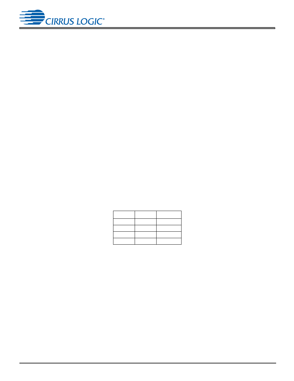
The Y-RAM and P-RAM share a single block of memory that includes three 2K word blocks (32 bits/word) that are
assignable to either Y-RAM or P-RAM as shown in Table 4.
Table 4-1. Memory Configurations for the C470xx
4.2.1
DMA Controller
The powerful 8-channel DMA controller can move data between 8 on-chip resources. Each resource has its own arbiter:
X, Y, and P RAMs/ROMs and the peripheral bus. Modulo and linear addressing modes are supported, with flexible start
address and increment controls. The service intervals for each DMA channel, as well as up to 6 interrupt events, are
programmable.
4.3 On-chip DSP Peripherals
4.3.1
Analog to Digital Converter Port (ADC)
The ADCs in the CS470xx devices feature dynamic range performance in excess of 100 dB. See
for more
details on CS470xx ADC performance. The CS47024 and CS47028 devices support up to 2 simultaneous channels of
analog-to-digital conversion with the input source selectable using an integrated 5:1 stereo analog mux (analog inputs
AIN_2A/B through AIN_6A/B). The CS47048 device adds a second pair of ADCs that are directly connected to input pins
AIN_1A/B providing a total of 4 simultaneous channels of analog-to-digital conversion. This feature gives the CS47048 the
ability to select from a total of six stereo pairs of analog input. A single programmable bit selects single-ended or differential
mode signals for all inputs. The conversions are performed with Fs=96 kHz.
P-RAM
X-RAM
Y-RAM
14K words 10K words
8K words
12K words 10K words
10K words
10K words 10K words
12K words
8K words 10K words
14K words