3 introduction to the color system, An374, Figure 1. color control system – Cirrus Logic AN374 User Manual
Page 6: Gain, Q3 = d, Q2 d, Q1 d
AN374
6
AN374REV2
3 Introduction to the Color System
The CS1630/31 is a two-channel TRIAC dimmable LED driver IC designed to change the color temperature of the
light output by independently varying the gains of the two different color LED strings to establish levels of color mix-
ing. This feature can be used to make the color temperature versus dim characteristics of the light similar to that of
an incandescent light bulb. In many such designs, one of the LED strings is composed of red or amber LEDs, and
the other string is composed of cool-white or blue-white LEDs. While the lumen output of white LEDs does not vary
significantly across temperature, the lumen output of red LEDs can vary as much as 40% across temperature. To
achieve a consistent light output across temperature, the current in the red LED string needs to be compensated
with respect to temperature. Depending on the design, either channel can be temperature compensated.
Cirrus Logic, Inc. and its affiliates and subsidiaries generally make no representations or warranties that the combi-
nation of Cirrus Logic’s products with light-emitting diodes (“LEDs”), converter materials, and/or other components
will not infringe any third-party patents, including any patents related to color mixing in LED lighting applications,
such as, for example, U.S. Patent No. 7,213,940 and related patents of Cree, Inc. For more information, please see
Cirrus Logic’s Terms and Conditions of Sale, or contact a Cirrus Logic sales representative.
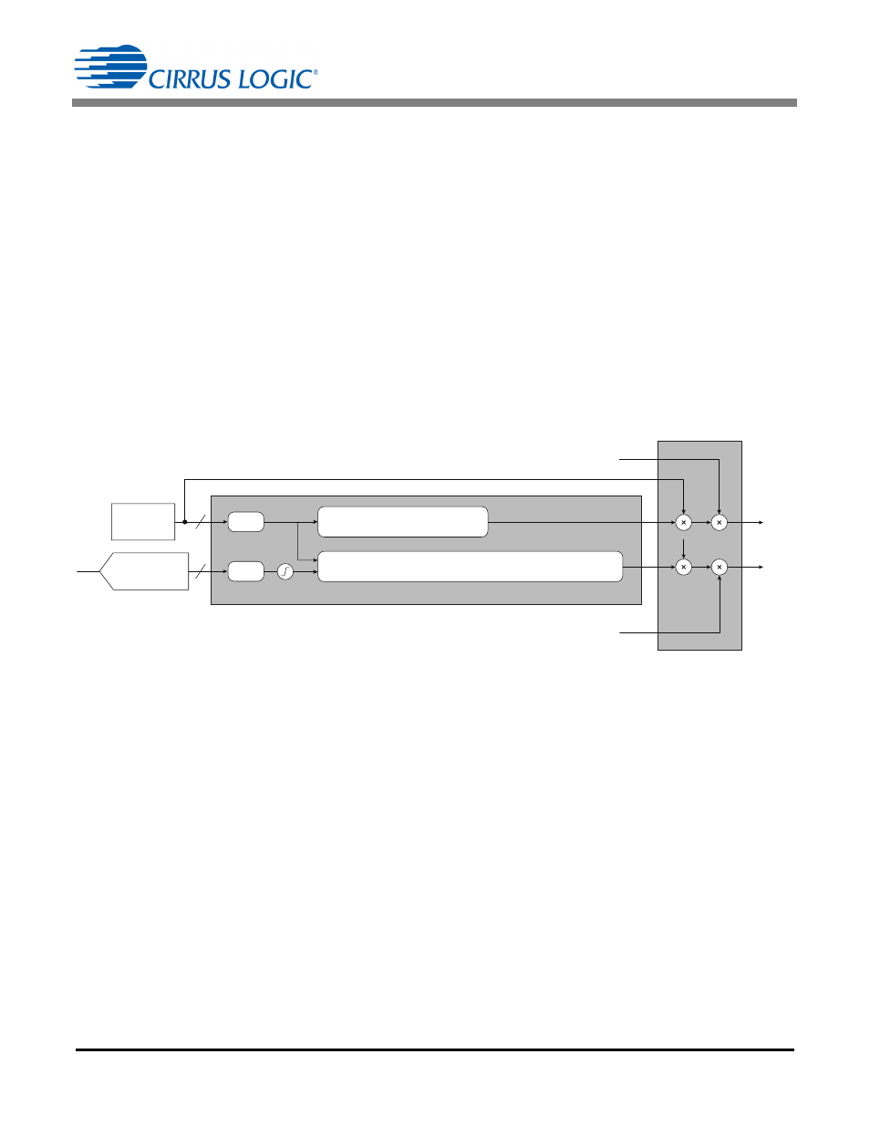
Figure 1 illustrates the block diagram of the color control block inside of the CS1630. The color temperature of the
light engine can be modified by changing the gains of each channel based on the current dim level. On the temper-
ature-controlled channel, the currents can be varied according to the temperature sensed by an external NTC.
The required gain value for a particular combination of dim and temperature is obtained using polynomial curves,
the coefficients of which are programmed into the CS1630/31 OTP memory. A different polynomial is used for each
channel. One of these is a polynomial in two variables, dim and temperature, while the other is a polynomial in dim
only. If D and T are assumed to be the normalized dim and temperature values, respectively, between 0 and 1.0,
then GAIN
DTR
refers to the dim-regulated gain and temperature-regulated gain, and GAIN
DR
refers to the dim-reg-
ulated gain.
As shown in Equation 1, the gain equation for the white is a third-order polynomial in dim, and the gain equation for
the red is a third-order polynomial in both dim and temperature. The color gain is third order to provide good tradeoffs
between computational overhead and being able to operate over the largest variety of LEDs across a wide range of
temperature. A lower-order polynomial fit, such as a quadratic or a linear fit, would not allow a large range of gain
values across the entire operating range. This would limit the sample space of available LEDs, since the gain is an
indirect reflection of its variation across temperature and required dim. As a result, a third-order fit allows the system
engineer to achieve a large variation in CCT and lumens across dim.
dim
NTC
(From Boost)
12
8
ч 4096
ч 256
D
T
Normalize
Normalize
Saturation
Logic
GAIN
DR
= Q3 × D
3
+ Q2 × D
2
+ Q1 × D + Q0
GAIN
DTR
= P30 × T
3
+ P20 × T
2
+ P10 × T + P03 × D
3
+ P02 × D
2
+ P01 × D +
P21 × T
2
× D + P12 × T × D
2
+ P11 × T × D + P00
I
White(ref)
I
Red(ref)
I
White
I
Red
dim
dim
Temperature
(ADC Fast Filter)
Figure 1. Color Control System
GAINDTR P30 T
3
P20 T
2
P10
+
+
T
P03 D
3
P02
+
+
D
2
P01 D
P21 T
2
D
+
+
=
P12 T D
2
P11 T D
P00
+
+
+
GAIN
DR
Q3
=
D
3
Q2 D
2
Q1 D
Q0
+
+
+
[Eq. 1]