An374, And v, Cross i – Cirrus Logic AN374 User Manual
Page 10: And i
AN374
10
AN374REV2
Step 1)
LED string configuration
Determine if a series configuration or a parallel configuration is a viable solution for the identified light engine.
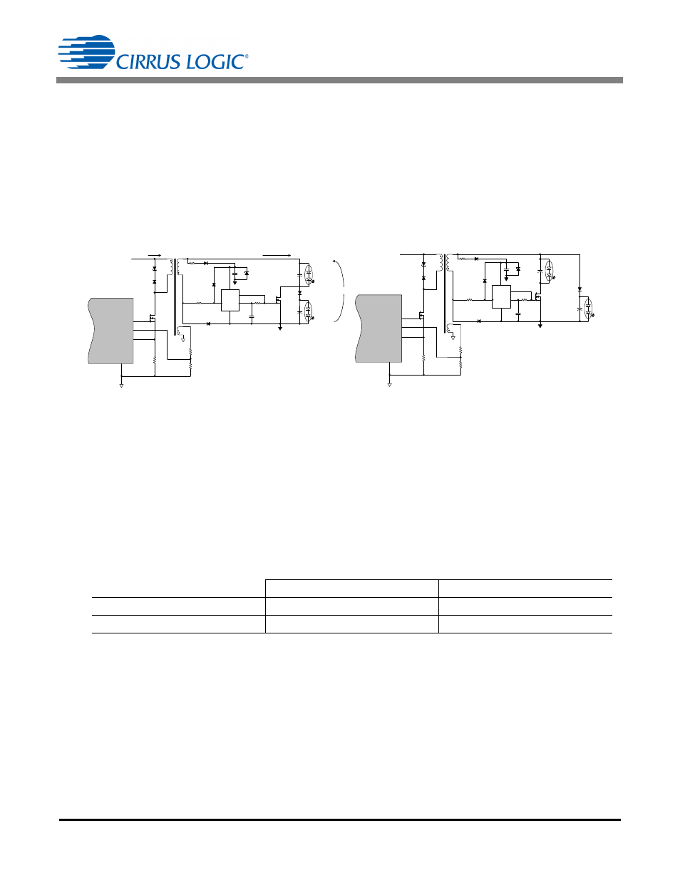
Figure 2a illustrates a series light configuration. The two LED strings are arranged in series so that current
passes through either one or both LED strings. A MOSFET is used to shunt current around one string on
alternating switching cycles. In this configuration, one string is required to have a larger current than the other
string. When considering a series design, it is recommended that the current flowing through one of the LED
channels be 80% or lower than that of the other LED channel at all times. The LED string that has current
flowing continuously is referred to as channel 1 LED (I
CH1
), while the string with the bypass FET is referred to
as channel 2 LED (I
CH2
); I
CH2
0.8
I
CH1
.
Figure 2b illustrates a parallel light configuration. The two LED strings are networked in parallel so that current
flows to either the channel 1 LED string or the channel 2 LED string at any given T2 time. The CS1630/31
controller uses the LED forward voltage to detect which LED string is being driven. One LED string must
always have a larger forward voltage compared to the other LED string. The LED string with the higher voltage
is referred to as channel 1 LED with forward voltage V
CH1
and the LED string with the lower voltage is referred
to as channel 2 LED with a forward voltage of V
CH2
.
A good rule of thumb is that channel 2 LED must always have a forward voltage of 85% or lower than the
channel 1 LED to consider a parallel design. Table 2 defines the selection process based on the requirements
of the series and parallel output configuration.
If there are problems converging on a target design using an existing light engine, the current and voltage
profile can be modified by adding, removing, or moving LEDs between the two LED channels. Figure 3
illustrates the parallel and series scenarios that can be configured using the CS163X Customer Application
tool.
V
CH2
< V
CH1
V
CH1
and V
CH2
Cross
I
CH2
< I
CH1
Series or Parallel Configuration
Series Configuration
I
CH1
and I
CH2
Cross
Parallel Configuration
Not Functional
Table 2. Series vs. Parallel
Figure 2a. Flyback Series Output Model
Figure 2b. Flyback Parallel Output Model
D2
R22
Z3
R21
R23
Q5
CS1630 /31
FBAUX
GND
13
GD
FBSENSE
15
12
11
TX1
V
B ST
R3
D6
U2
C10
C8
C15
D5
D
GND
_
Q
V CC
D15
R12
D10
Q3
R2
C16
Channel 1 LED
(White)
Channel 2 LED
(Red)
GND
IGND
I
MODE x
I
P RI
V
MODE x
D9
D2
R22
Z2
R21
R23
Q5
CS1630 /31
FBAUX
GND
13
GD
FBSENSE
15
12
11
TX1
V
B S T
R3
D6
U2
C10
C15
C8
D5
D
GND
_
Q
V CC
D15
R12
D10
Q3
R2
C16
Channel 1 LED
(White)
Channel 2 LED
(Red)
GND
IGND
D9