An374 – Cirrus Logic AN374 User Manual
Page 13
AN374
AN374REV2
13
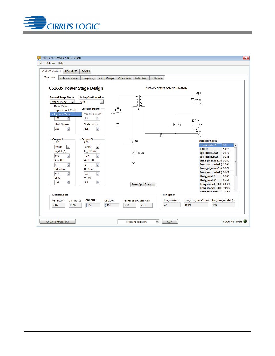
Figure 5 illustrates the process used to select the second stage flyback mode using the CS1630/31 system
design utility.
The CS1630/31 has a minimum required T1 time that is dependent on leading edge blanking time T
LEB
.
Blanking time T
LEB
is programmable from 150ns to 800ns and is used to effectively disable the peak current
comparator from turning off the gate drive too early due to spurious switching noise. In applied systems, a good
rule of thumb is to target a minimum duty cycle of 10% or greater.
Step 3) General considerations for all topology
1. In the series configurations, the current in one string will always be higher than the current in the second
string across the entire dim and temperature range. There are specific advantages to using the series con-
figuration if the light engine specifications comply with the constraints. In Mode 1, the phase synchronizer
MOSFET is ‘OFF’ and the output power P
MODE1
delivered to the load in a series design is calculated using
Figure 5. Selecting the Second Stage Mode Using the CS1630/31 System Design Utility
P
MODE1
V
CH1
V
CH2
+
I
CH2
=
[Eq. 7]