Nels. figure 3, An374 – Cirrus Logic AN374 User Manual
Page 11
AN374
AN374REV2
11
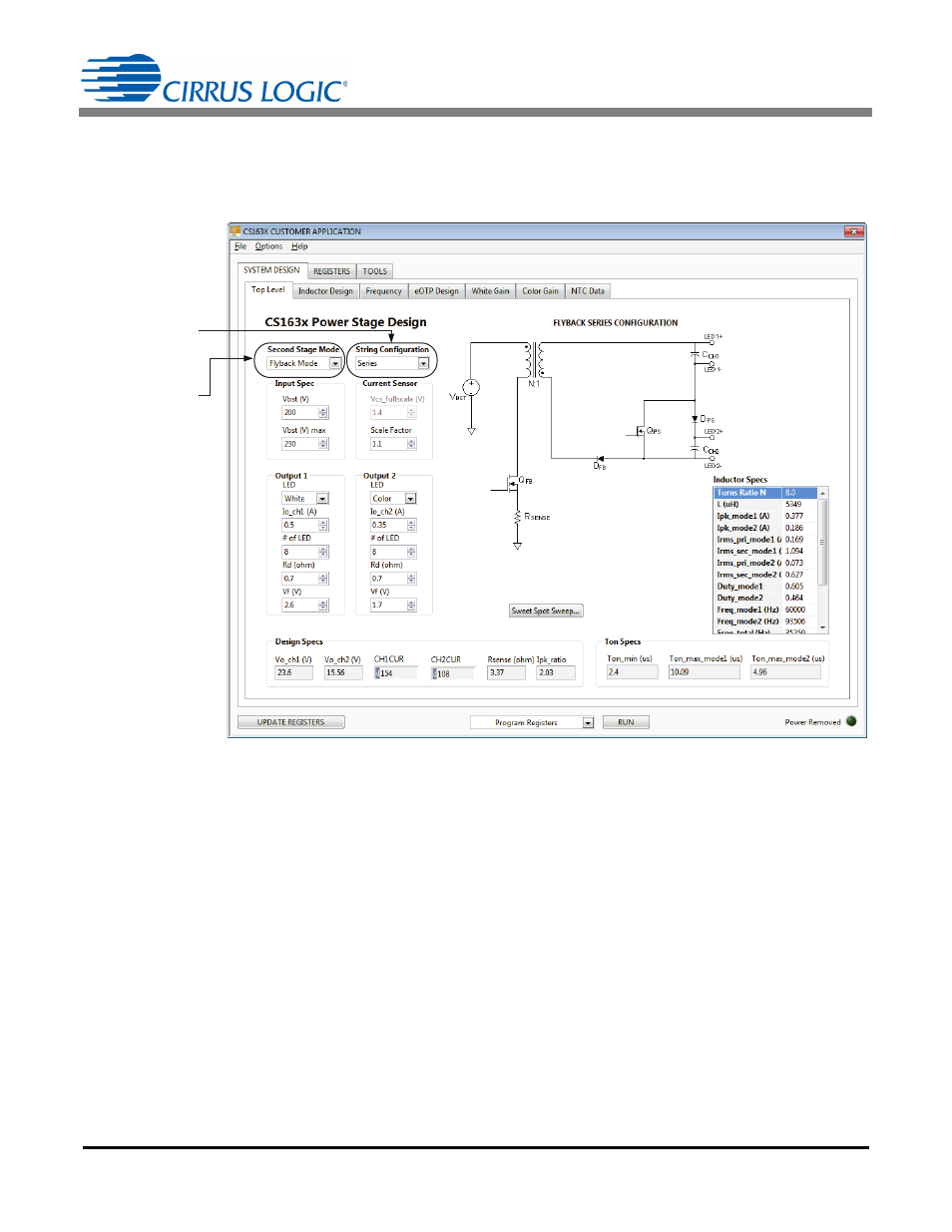
Bit STRING in register Config3 at address 7 selects the second stage output channel configuration. When bit
STRING is set to ‘1’ a series configuration is selected. Figure 3 illustrates the process used to select the
second stage flyback mode using the CS163X system design application.
Step 2) Select power train topology
The CS1630/31 supports three possible power train configurations: tapped buck, buck, and flyback (see
Figure 4a, 4b, and 4c). The two most important factors for selecting a power train configuration is whether the
output requires Underwriters Laboratory (UL) approved isolation and the input to output voltage ratio. The
flyback power train can be either isolated or non-isolated. Buck and tapped-buck designs are expected to
always be non-isolated. If isolation is not required, one of the three possible solutions must be selected. If
isolation is required, the design will be a flyback.
Step 2a:
Select Series
vs. Parallel
Step 2b:
Select Flyback,
Buck, or
Tapped Buck
Figure 3. Second Stage String Configuration