3 synchronizer design considerations, 4 constraints on the boost stage, An374 – Cirrus Logic AN374 User Manual
Page 17
AN374
AN374REV2
17
4.3 Synchronizer Design Considerations
The synchronizer circuit drives an external MOSFET, which may be ground referenced depending on the topology.
Constraint 1: Non-isolated synchronizer circuit considerations
In the case of a non-isolated flyback, the secondary ground of the flyback can be referenced to the primary
ground thereby having the least expensive synchronous circuit solution consisting of the synchronous
MOSFET and the diode. The MOSFET is directly driven from the SYNC pin of the CS1630/31.
In the case of the buck topology, the outputs are referenced to link voltage and the following two options are
possible:
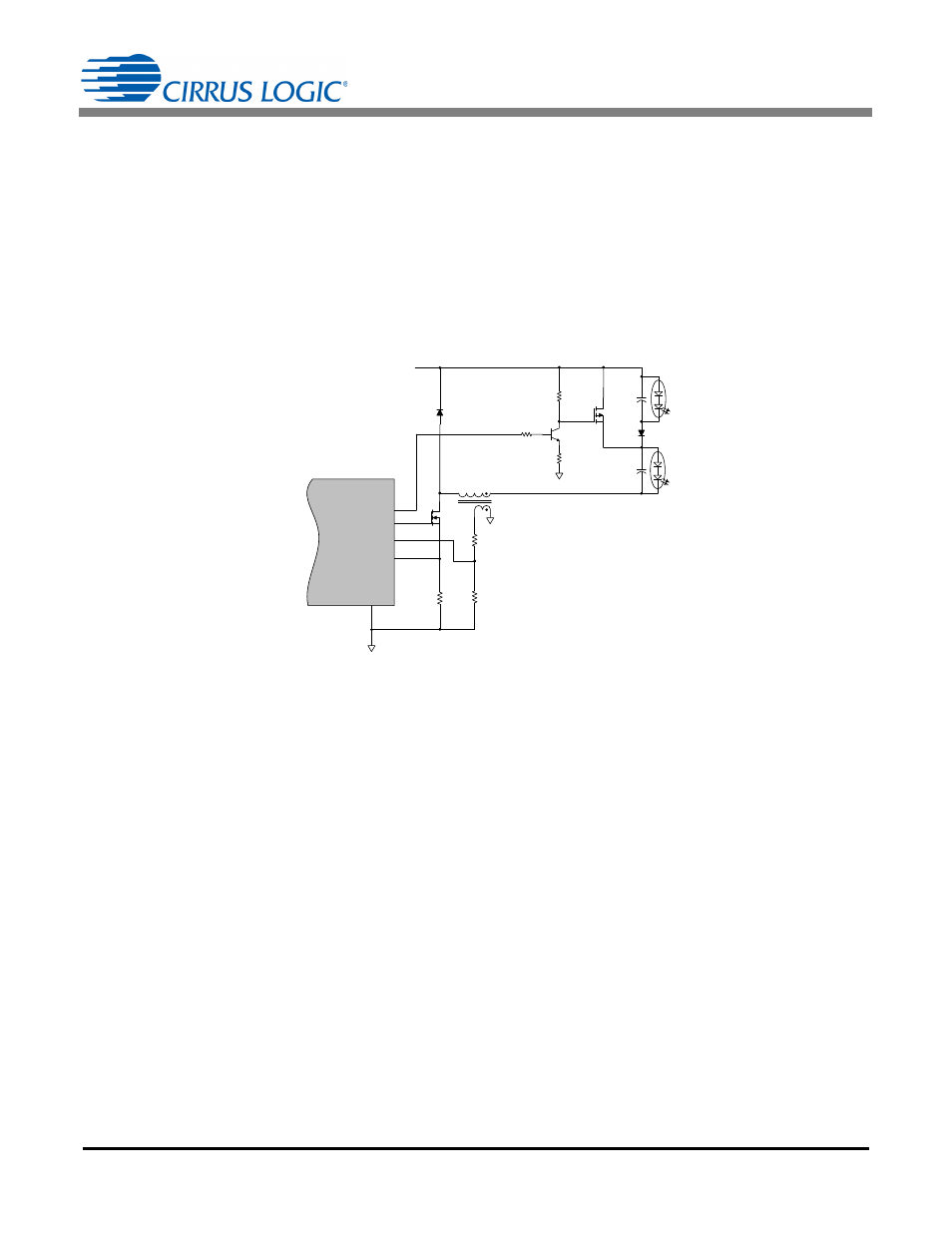
1. Level shifting the SYNC pin output to a higher voltage using an external BJT and a P-channel MOSFET
(see Figure 7).
2. Driving the synchronizer externally using flip-flop from the switching node or another winding off of the
buck converter.
4.4 Constraints on the Boost Stage
Constraint 1: Maximum power should be power at full AC sine wave
It is recommended to design the dimming curve such that the maximum output power is delivered to the load
at 100% brightness when the driver is behind the full AC sine wave.
Constraint 2: Power should be monotonically increasing
The output power in the driver should be close to monotonically increasing. If the available power from the
dimmer cut waveform at any conduction angle is smaller than the requested output power, then the link voltage
may not be in regulation at that conduction angle. In such a case, the peak currents on the boost inductor need
to be increased, and all design calculations mentioned in application note AN368 are no longer valid for that
particular design. Increasing peak currents may compromise EMI and efficiency.
R22
R21
R23
Q4
L3
CS1630 /31
FBAUX
GND
13
GD
FBSENSE
15
12
11
D3
V
B S T
C16
C15
D11
R27
Channel 1 LED
(White)
Channel 2 LED
(Red)
GND
R25
Q6
R26
SYNC
Q5
GND
Figure 7. Non-isolated Synchronizer Buck Series Output Model