An374 – Cirrus Logic AN374 User Manual
Page 15
AN374
AN374REV2
15
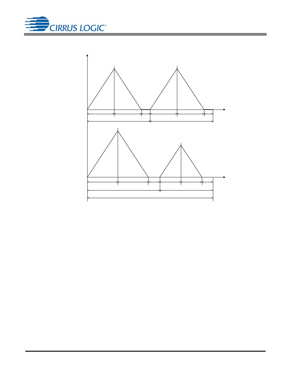
Figure 6 illustrates the current comparison through the inductor. In this case, the buck is chosen to explain
the point. The same logic can be extended to the flyback topology as well.
In a single-string design, power P
OUT(single)
delivered in the first switching period TT equals power deliv-
ered in the second switching period and the total power is equal to two times power P
OUT(single)
. In a two-
channel design, the total power P
OUT(dual)
is approximately equal to:
The above equation yields Equation 12:
where
= P
MODE2
/P
MODE1
The size of the inductor depends on the amount of energy stored at a first-order approximation. The energy
stored in the inductor of a single string system is equal to P
OUT(single)
F
sw
. The maximum energy stored
in the inductor of a two string system is equal to P
MODE1
F
sw1
. The size factor
of the inductor is defined
by:
From Equation 13, it can be seen that the inductor for a CS1630/31-based equivalent system will be
times larger.
Power Transferred in a Single String Controller
Power Transferred in a Two String Controller with
Unequal Balance between Two Strings
t
i(t)
T1
T2
TT
T3
T1
T2
TT
T3
TT
T1
CH1
T2
CH 1
TT
CH 1
T3
CH1
T1
CH2
T2
CH2
TT
CH2
T3
CH 2
t
Figure 6. Current Comparison through the Inductor
P
OUT dual
P
MODE1
P
MODE2
+
=
2 P
OUT
gle
sin
[Eq. 11]
P
MODE1
P
OUT
gle
sin
-----------------------------
2
1
+
------------------
[Eq. 12]
2 F
sw
1
+
F
sw1
------------------------------------
[Eq. 13]