An374 – Cirrus Logic AN374 User Manual
Page 33
AN374
AN374REV2
33
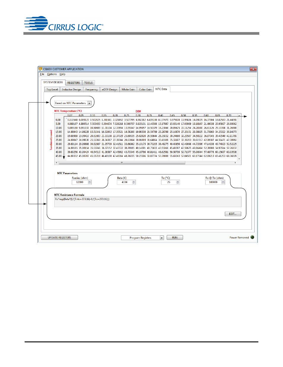
Step 3) NTC setting
In Figure 29, the value can be entered as an NTC parameter, which corresponds to temperature or in
resistances themselves. In addition, the resistance in series to the NTC should be specified. Check application
note AN368 for schematic and typical connection to the eOTP pin.
Once the gains are computed, note that the UPDATE REGISTERS button does write the registers to the IC.
At this point, connect the I
2
C connections and click the Write All Registers button from the drop-down list in
the bottom of the tab page, and click the RUN button. See application note AN369 for more information about
the CS1630/31 application software.
7.2 Register Bits in OTP Map Affected by the Curve Fitter
The following bits need to be set based on the data collected:
• The second stage minimum dim value may be changed as a result of remapping the dim axis (S2DIM).
Refer to application note AN368 for more information about how to recalculate it.
• Bits HI_SAT[2:0] and LOW_SAT[2:0]: By default, HI_SAT[2:0] is set at the eOTP threshold. If the eOTP
threshold is much higher than the highest NTC temperature in the operating range, then the value can be
clipped to the highest temperature with a little margin on top for accuracy considerations. The codes can
be directly specified if the spreadsheet is constructed in the manner specified previously.
Figure 29. SYSTEM DESIGN - NTC Data Tab