Function of the test circuit for 2-wire, Cable connection in the spring clip terminal – WIKA IS-21-F User Manual
Page 7
2132926.07 GB/D/F/E 03/2010
12 WIKA Operating instructions/Betriebsanleitung/Mode d'emploi/Instrucciones de servicio IS-2X
2132926.07 GB/D/F/E 03/2010
13
WIKA Operating instructions/Betriebsanleitung/Mode d'emploi/Instrucciones de servicio IS-2X
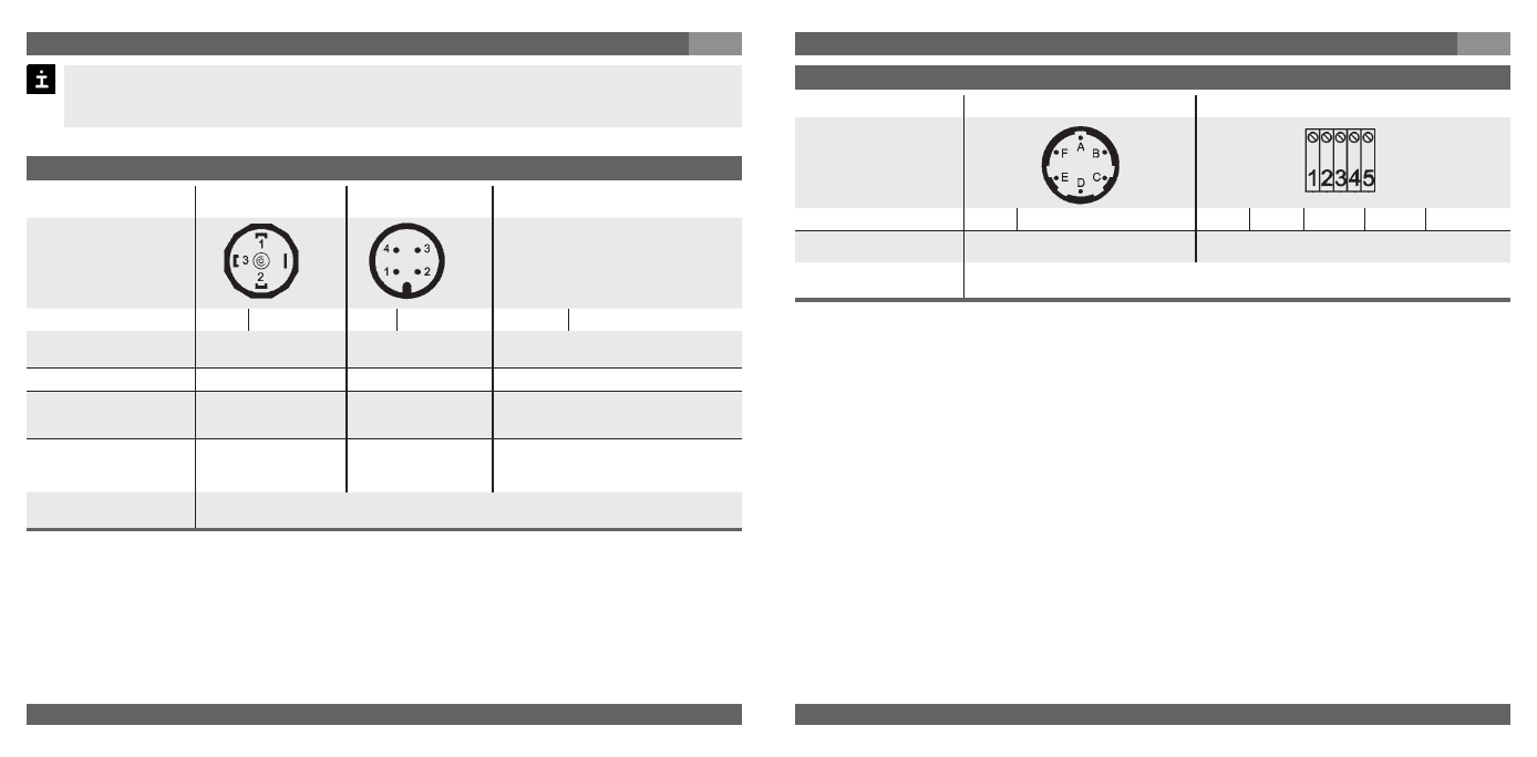
Wiring details
Bayonet connector, 6-pin
Field case (with internal spring clip terminals)
2-wire
U+ = A U- = B
U+ = 1 U- = 2
Test+ = 3 Test- = 4 Screen = 5
Ingress Protection
per IEC 60 529
IP 65 (NEMA 4)
IP 67
The ingress protection classes specified only apply while the pressure transmitter is
connected with female connectors that provide the corresponding ingress protection.
Wiring details
L-Connector
DIN 175301-803 A
CIrcular connector
M12x1, 4-pin
Flying leads,
1.5 m
2-wire
U+ = 1 U- = 2
U+ = 1 U- = 3
U+ = brown U- = green
Cable screen
PUR-cable: grey
FEP-cable: twisted and tinned
Wire gauge
up to max. 1.5 mm
2
-
0.5 mm
2
(AWG 20)
Diamter of cable
6 to 8 mm
ship approval:
10 to 14 mm
-
6.8 mm (Code DL / EM)
7.5 mm (Code DM)
Ingress Protection
per IEC 60 529
IP 65
IP 67
IP 67 - Order code: DL
IP 68 zero/span not adjustable-
Order code: EM / DM
The ingress protection classes specified only apply while the pressure transmitter is
connected with female connectors that provide the corresponding ingress protection.
7. Starting, operation
GB
With a line transformer you realise the mandatory galvanic isolation of the voltage and
current supply between hazardous and non-hazardous areas and ensure the safety
connection data.
7. Starting, operation
GB
Function of the test circuit
for 2-wire:
By means of the test circuit the current
can be metered during normal opera-
tion without having to disconnect the
instrument. For that purpose you have
to connect an ammeter (for appli-
cations in hazardous areas; internal
resistance < 15 Ohm) to the test
+/- terminals.
Cable connection in the spring clip terminal
Cover the stripped wire ends with end splices.
Unscrew the case cover.
Loosen the cable gland using an open-end
wrench, wrench size 24.
Lead the cable through the cable gland into
the opened case head.
Press the corresponding plastic lever at the
spring clip terminal down using a screw driver,
so that the clamped contact will be released.
Lead the prepared flying lead into the opening
and let go of the plastic lever, so that the flying
lead will be squeezed inside the spring clip
terminal.
After connecting the individual wires, tighten
the cable gland and screw down the case
over.
Model IS-20-F, IS-21-F, IS-20-H with field case: