WIKA IS-21-F User Manual
Page 6
2132926.07 GB/D/F/E 03/2010
10 WIKA Operating instructions/Betriebsanleitung/Mode d'emploi/Instrucciones de servicio IS-2X
2132926.07 GB/D/F/E 03/2010
11
WIKA Operating instructions/Betriebsanleitung/Mode d'emploi/Instrucciones de servicio IS-2X
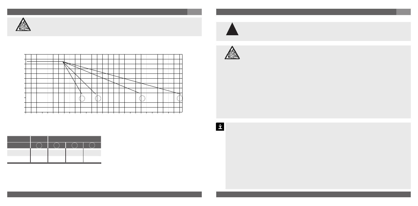
Model
IS-20-H
IS-2X-S /-F
Version
A
B
C
D
Cooling fin
-
2
3
5
Constant K
0.34
0.47
0.68
0.76
A B C D
0
10
20
30
40
50
60
70
80
90
100
110
120
40
80
120
160
200
240
280
320
7. Starting, operation
GB
Operate the pressure transmitter with a shielded cable and earth the shield at least
on one side of the cable, if the cable is longer than 30 m or if it is run outside of the
building.
Ingress protection per IEC 60529 (The ingress protection classes specified only apply
while the pressure transmitter is connected with female connectors that provide the
corresponding ingress protection).
Ensure that the cable diameter you select fits to the cable gland of the connector
Ensure that the cable gland of the mounted connector is positioned correctly and
that the sealings are available and undamaged. Tighten the threaded connection and
check the correct position of the sealings in order to ensure the ingress protection.
Please make sure that the ends of cables with flying leads do not allow any ingress of
moisture.
Electrical connection
Ground the cable screen at one end, preferably in the safe, thus non-Ex,
area (EN 60079-14). For devices with flying leads, the screen is connected
to the housing. The simultaneous connection of housing and cable screen
to ground is only permitted if ground loop problems between the screen
connection (e.g. at the power supply) and housing can be excluded
(see EN 60079-14).
Supply the pressure transmitter from an intrinsically safe current circuit (Ex ia).
Consider both the internal capacitance and inductance.
Cover flying leads with fine wires by an end splice (cable preparation).
The bayonet-connector is made of light metal, a material which is not permissible for
group I applications (mining).
Consider that cables for use in
zones 1 and 2 must be checked with a test voltage
between conductor/earth, conductor/screen, screen/earth of more than 500V (AC).
Earth the housing, through the process connection, against electromagnetic
fields and electrostatic discharge.
7. Starting, operation
GB
Relation of medium temperature to ambient temperature
Calculation of max. temperature of
ambience:
T
amb
= T
med
+ (T
B
- T
med
) / K
Calculation of cooling element:
T
B
= T
med
- (T
med
- T
amb
) x K
T
B
= Operation temperature of transmitter
T
med
= max. temperature of process medium
T
amb
= max. temperature of ambience
K = Constant of cooling element
Temperatur
e of ambient (°C)
Temperature of medium (°C)
Ensure that, particularly in the dust hazardous area, the cooling elements
will not be contaminated and that no dust can be deposited on them,
because otherwise the cooling effect cannot be guaranteed.
Warning
!
Warning
Advertencia