Kramer Electronics VP-4x1CS User Manual
Page 31
28
VP-4x1CS - Kramer Protocol 2000
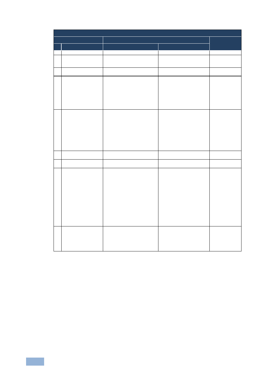
Instruction Codes for Protocol 2000
Instruction
Definition for Specific Instruction
Notes
# Description
Input
Output
0
RESET VIDEO
0
0
1
1
SWITCH VIDEO
Set equal to video input that is
switched
(0 = disconnect)
Set equal to video output that
is switched
(0 = to all the outputs)
2, 15
5
REQUEST STATUS
OF A VIDEO OUTPUT
Set as SETUP #
Equal to output number
whose status is required
4, 3
15 REQUEST WHETHER
SETUP IS DEFINED /
VALID INPUT IS
DETECTED
SETUP #
or
Input #
or
Output #
0
– For checking if setup is
defined
1
– For checking if input is
valid
2
– For checking if output is
valid
3
– For checking if EDID
output is valid
8
16 ERROR / BUSY
For invalid / valid input (i.e.
OUTPUT byte = 4 or OUTPUT
byte = 5),
this byte is set as the input #;
For invalid / valid output (i.e.
OUTPUT byte=7 or OUTPUT
byte=8), this byte is set as the
output#
0
– Error
1
– Invalid instruction
2
– Out of range
3
– Machine busy
4
– Invalid input
5
– Valid input
6
– RX buffer overflow
7
– Invalid output
8
– Valid output
9
– Valid EDID
9, 25
30 LOCK FRONT PANEL
0
– Unlock panel
1
– Lock panel
0
2
31 REQUEST WHETHER
PANEL IS LOCKED
0
0
16
61 IDENTIFY MACHINE
1
– Video machine name
2
– Audio machine name
3
– Video software version
4
– Audio software version
5
– RS-422 controller name
6
– RS-422 controller version
7
– Remote control name
8
– Remote software version
9
– Protocol 2000 revision
10
– Control data machine name
11
– Control data software
version
For names:
0
– Request first 4 digits
1
– Request first suffix
2
– Request second suffix
3
– Request third suffix
10
– Request first prefix
11
– Request second prefix
12
– Request third prefix
For versions:
0
– Main board
or the number of external
board
13
62 DEFINE MACHINE
1
– Number of inputs
2
– Number of outputs
3
– Number of setups
1
– For video
2
– For audio
3
– For SDI
4
– For remote panel
5
– For RS-422 controller
6
– For control data
14
Notes on the above table:
NOTE 1 - When the master switcher is reset, (e.g. when it is turned on), the reset code is sent to the PC. If this code is
sent to the switchers, it resets according to the present power-down settings.
NOTE 2 - These are bi-directional definitions. That is, if the switcher receives the code, it performs the instruction; and if
the instruction is performed (due to a keystroke operation on the front panel), then these codes are sent. For example, if
the HEX code:
01
85
88
83
was sent from the PC, then the switcher (machine 3) switches input 5 to output 8. If the user switched input 1 to output 7
via the front panel keypad, then the switcher sends HEX codes:
41
81
87
83
to the PC.
When the PC sends one of the commands in this group to the switcher, then, if the instruction is valid, the switcher
replies by sending to the PC the same four bytes that it was sent (except for the first byte, where the DESTINATION bit
is set high).
NOTE 3 - SETUP # 0 is the present setting. SETUP # 1 and higher are the settings saved in the switcher's memory, (i.e.
those used for Store and Recall).