Alarms – Bell & Gossett 10-001-278 XLS Integrated Pump Controller User Manual
Page 12
12
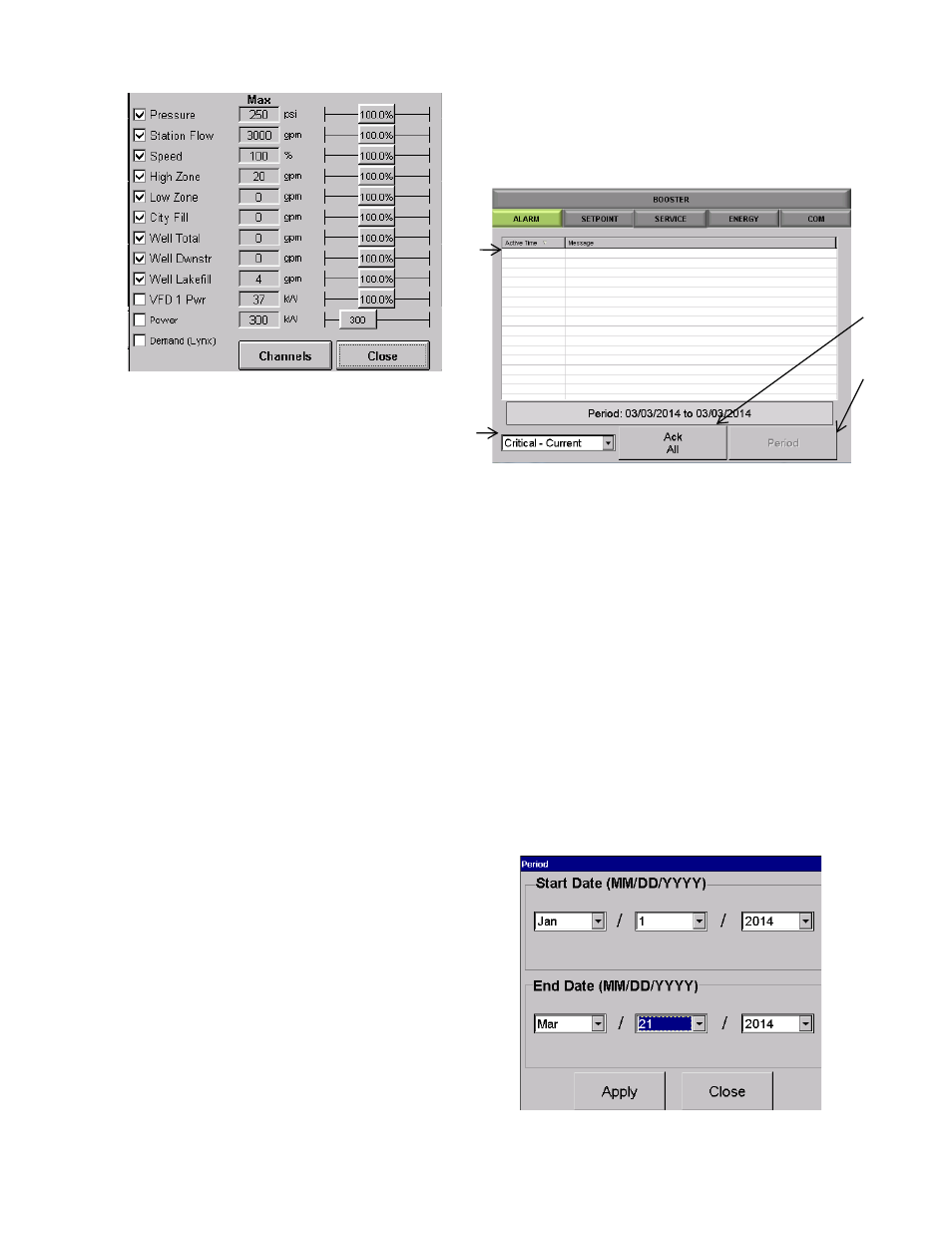
Figure 2 2 : Configure Data
Check the box next to the data you want to
show. Not all data is available for all systems.
Use the slider bar on the right to adjust the
graph scaling to a value that makes it most
comfortable to read.
100% means the graph scale is the same as
the analog scaling max value. 110% means
the graph scaling is 110% of the analog max
scaling for the channel. The exception here is
the KW reading, which is an absolute number
because KW is read directly, rather than
scaled.
Click “Channels” to access the calibration
screen directly from the “Configure Data”
screen.
This screen is accessible also from “Setup”-
>”Options Setup” and is discussed in detail
in that section.
ALARMS
The [ALARMS] tab will take you to the Alarms detail
screen.
Figure 2 3 : Alarms Home Screen
a. The Alarm history field will display particular alarms
based on the drop down selection detail in (b). The
time of the alarm and the type of alarm will be
displayed.
b. Drop down selection that will allow you to sort
alarms
i.
Critical – Current (current day)
ii.
Critical – History
iii.
Non-Critical
c. The [Ack All] button will clear any alarms that are
currently active.
d. Tapping [Period], available in ‘Critical – History” and
“Non-Critical” modes, will open an enhanced screen
shown in Figure 24 to allow for the display of only
alarms during a given range.
Figure 24: Period Screen
a
b
c
d