Goulds Pumps 3298 - IOM User Manual
Page 77
Maintenance
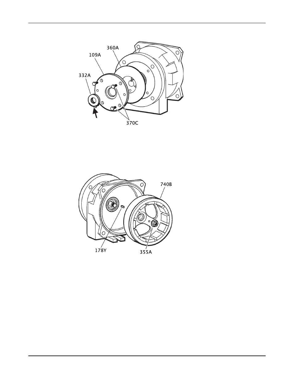
6. Install the bearing-end cover gasket (360A) and bearing end cover (109A) with hex
capscrews (370C).
Figure 67: Bearing frame assembly
7. Press the labyrinth seal (332A) into the end cover (109A):
a) Make sure that the O-rings are in grooves of labyrinth seal.
b) Orient the expulsion ports to the 6 o’clock position and press the seal into the bearing
end cover (109A) until it is shouldered against the end cover.
No adjustment is necessary.
8. Install the key (178Y) on the shaft (122B).
Figure 68: Drive magnet assembly
9. Install the magnet assembly (740B) onto the shaft (122B).
10. Place a shaft wrench on the drive shaft (122B). Install a hex nut (355A) and tighten the nut
per the Bolt torque values table in the Reassembly section of the Maintenance chapter.
11. For the M and L groups, complete these steps:
a) Install the rub ring (144A) into the bearing frame (228).
b) Line up the hole in the rub ring with the tapped hole in the frame (228) by using the
scribed mark on the rub ring to reference the tapped hole in the frame.
c) Lightly tap the rub ring (144A) with a rubber mallet until it shoulders into the bearing
frame (228).
3298 Family Installation, Operation, and Maintenance Manual
75