Type, Dppo, Vn vni i i it t t t – NOVUS Controller N1100 User Manual
Page 6: Offs, Spll, Spxl, Rsll, Rsxl, Bavd, Addr
Controller N1100
NOVUS AUTOMATION
6/8
CONFIGURATION CYCLE
type
type
type
type
INPUT TYPE: Selects the input signal type to be connected
to the process variable input. Refer to Table 1.
This is the first parameter to be set.
dppo
dppo
dppo
dppo
DECIMAL POINT POSITION: For input types 16, 17, 18 or
19 only. Selects the decimal point position to be viewed in
both PV and SV.
vn
vn
vn
vnI
I
I
It
t
t
t
TEMPERATURE INDICATION IN ºC OR ºF: Selects the
display indication to be in ºC or ºF. Only available if input
type is other than 16, 17, 18 or 19.
offs
offs
offs
offs
SENSOR OFFSET: Offset value to be added to the PV to
compensate sensor error. Default value: zero.
spll
spll
spll
spll
SET POINT LOW LIMIT:
- Linear inputs: Sets the lower range for SV and PV
indication.
- T/C and Pt100 inputs: sets the lower range for SV.
spxl
spxl
spxl
spxl
SET POINT HIGH LIMIT:
- Linear inputs: Sets the upper range for SV and PV
indication.
- T/C and Pt100 inputs: sets the upper range for SV.
rsll
rsll
rsll
rsll
REMOTE SET POINT LOW LIMIT: Selects the lower range
for indication of the Remote Setpoint.
rsxl
rsxl
rsxl
rsxl
REMOTE SET POINT HIGH LIMIT: Selects the upper
range for indication of the Remote Setpoint.
bavd
bavd
bavd
bavd
DIGITAL COMMUNICATON BAUD RATE SELECTION:
0: 1200 bps; 1: 2400 bps; 2: 4800 bps; 3: 9600 bps; 4:
19200 bps.
addr
addr
addr
addr
SLAVE ADDRESS SELECTION: Identifies a slave in the
network. The possible address numbers are from 1 to 247.
I/O CYCLE (INPUTS AND OUTPUTS)
I
I
I
Io 1
o 1
o 1
o 1
I/O 1 FUNCTION: Selects the I/O function to be used at I/O
1 (relay 1). Options 0 to 5 are possible for this output. It is
normally used as option 5, PWM main control output. Refer
to Table 2 for functions.
I
I
I
Io 2
o 2
o 2
o 2
I/O 2 FUNCTION: Selects the I/O function to be used at I/O
2 (relay 2). Options 0 to 5 are available. This output is
normally used as alarm output. See Table 2 for functions.
I
I
I
Io 3
o 3
o 3
o 3
I/O 3 FUNCTION: Selects the I/O function to be used at I/O
3 (option 1). I/O 3 can be a relay output or a digital
input/output. Functions 0 to 10 are available. Refer to
Table 2 for functions. The presence of this I/O option is
detected by the controller and the prompt menu will only be
shown if the expansion option is available.
I
I
I
Io 4
o 4
o 4
o 4
I/O 4 FUNCTION: Selects the I/O function to be used at I/O
4 (option 2). I/O 4 can be a digital input/output. Functions 0
to 10 are available. Refer to Table 2 for functions. The
prompt menu will only be shown if the expansion option is
present.
I
I
I
Io 5
o 5
o 5
o 5
I/O 5 FUNCTION: Selects the I/O function to be used at I/O
5 (Analog Output). Functions 0 to 15 are available (See
Table 2). This option is normally used for main control
output or PV analog retransmission.
CALIBRATION CYCLE
All input and output types are factory calibrated. This cycle should
only be accessed by experienced personnel. If in doubt do not press
the
or
keys in this cycle.
Inl(
Inl(
Inl(
Inl(
INPUT LOW CALIBRATION: Sets the Process Variable low
calibration (offset). Several keystrokes at
or
might
be necessary to increment one digit.
Inx(
Inx(
Inx(
Inx(
INPUT HIGH CALIBRATION: Sets the Process Variable
span calibration (gain).
ovll
ovll
ovll
ovll
OUTPUT LOW CALIBRATION: Sets the analog current
output low calibration (offset).
Ovx(
Ovx(
Ovx(
Ovx(
OUTPUT HIGH CALIBRATION: Sets the analog current
output span calibration (gain).
(j l
(j l
(j l
(j l
COLD JUNCTION OFFSET CALIBRATION: Sets the cold
junction offset calibration.
xtyp
xtyp
xtyp
xtyp
HARDWARE TYPE: Configures the controller to recognize
the actual installed optional hardware (accessories). The
parameters menu will show the parameters relative to the
optional hardware:
0
0
0
0 - no optionals or c/ RS485 only;
1
1
1
1 - relay 3 (I/O 3);
2
2
2
2 - Digital I/O (2 inputs/outputs: I/O3 and I/O4);
3
3
3
3 - Heater break protection (option);
Rsl(
Rsl(
Rsl(
Rsl(
REMOTE SET POINT LOW CALIBRATION: Sets the
Remote Set Point low calibration (offset). Several
keystrokes at
or
might be necessary to increment
one digit.
Rsx(
Rsx(
Rsx(
Rsx(
REMOTE SET POINT HIGH CALIBRATION: Sets the
Remote Set Point span calibration (gain).
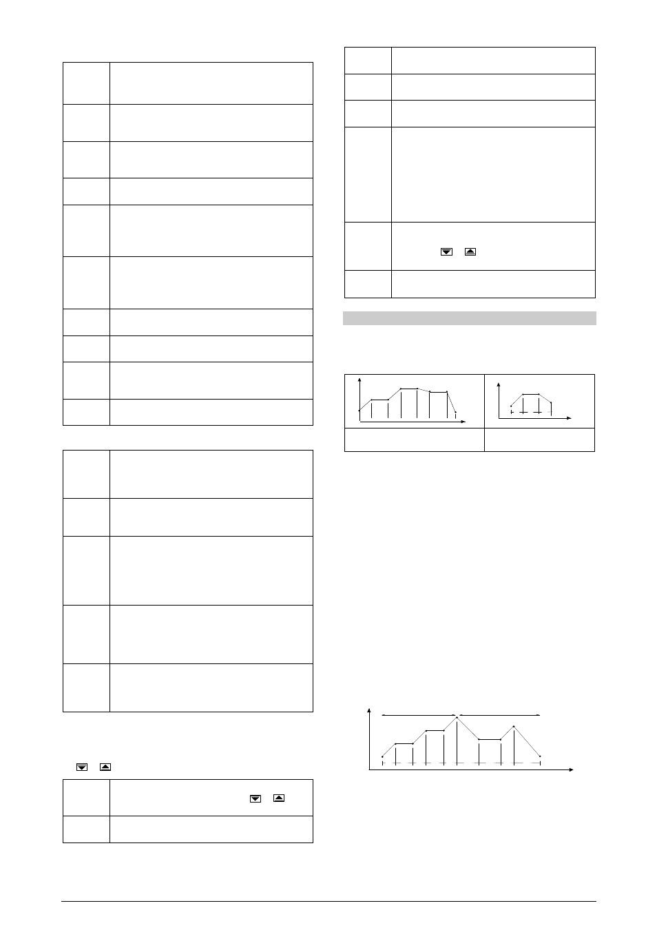
RAMP AND SOAK PROFILE PROGRAM
Seven ramp and soak profiles with up to 7 segments each can be
programmed. Longer profiles of up to 49 segments can be created by
linking 2 or more profiles.
SP
tim e
T 1
T2
T3
T4
T5
SP0
SP1
SP2
S P3
SP 4
SP5
SP6
SP7
T6
T 7
SV
time
T1
T2
T3
SP0
SP1
SP2
SP3
T4=0
Figure 11 - Example of a complete ramp and
soak profile
Figure 12 - Example of a profile with
fewer segments. (T4 is set 0)
To execute a profile with fewer segments just program 0 (zero) for the
time intervals that follow the last segment to be executed.
The program tolerance “Ptol
Ptol
Ptol
Ptol” defines the maximum deviation
between PV and SV for the execution of the profile. If this deviation is
exceeded, the program will be interrupted until the deviation falls to
within the tolerance band.
Programming 0 (zero) at this prompt disables the tolerance and the
profile execution will not to be halted even if PV does not follow SV
(time priority as opposed to SV priority).
LINK OF PROGRAMS
It is possible to create a more complex program, with up to 49
segments, joining the seven programs. This way, at the end of a
program execution the controller immediately starts to run another one.
When a program is created, it must be defined in the “LP
LP
LP
LP" screen
whether there will be or not another program.
To make the controller run a given program or many programs
continuously, it is only necessary to link a program to itself or the last
program to the first.
SV
time
T1
T2
T3
T4
T5
T1
T2
T3
T4
SP0
SP1
SP2
SP3
SP4
SP5 / SP0
SP1 SP2
SP3
SP4
Program 1
Program 2
Figure 13 - Example of two linked programs