NOVUS Controller N1100 User Manual
Page 3
Controller N1100
NOVUS AUTOMATION
3/8
CONFIGURATION
INPUT TYPE SELECTION
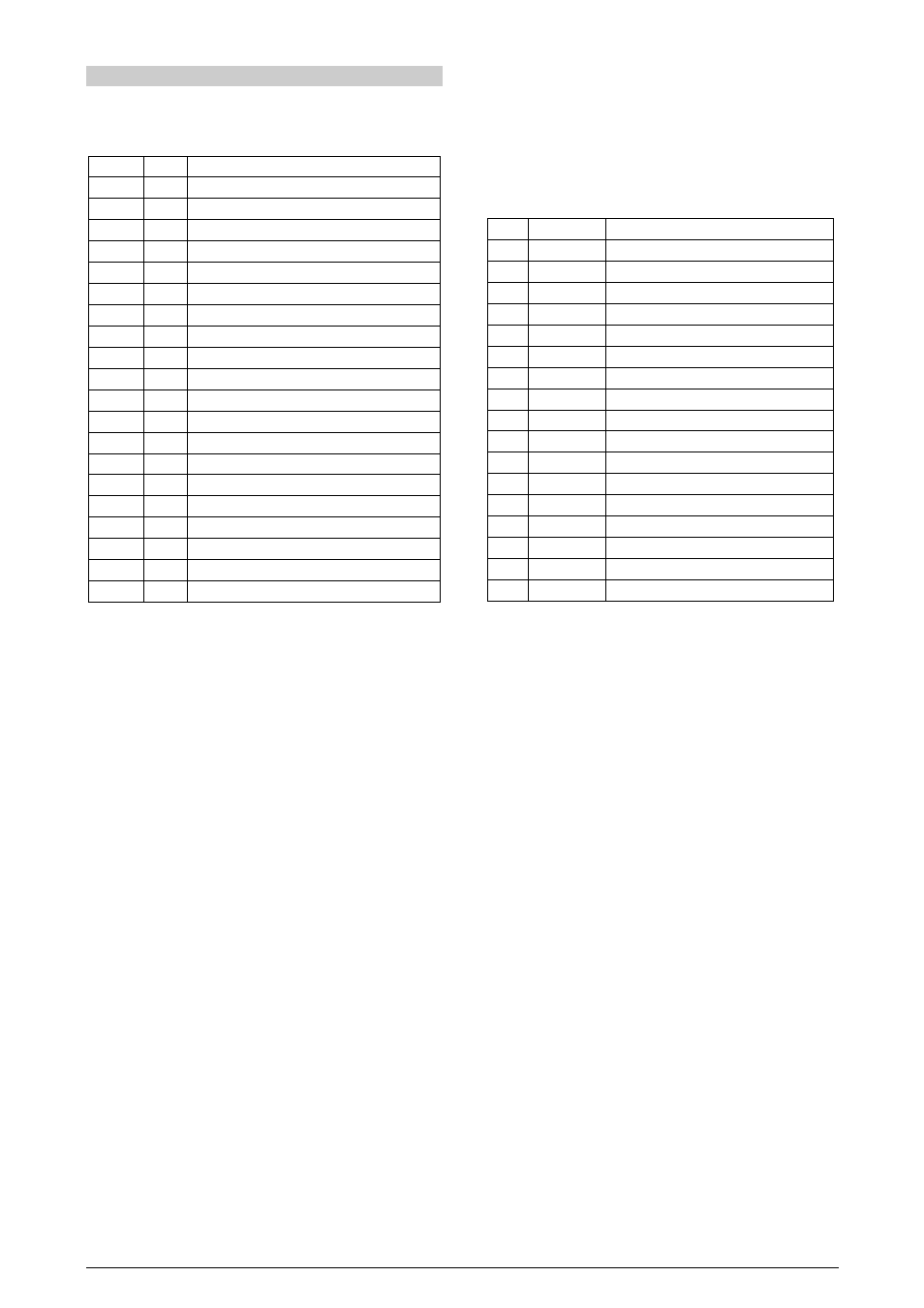
Select the input type (in parameter “tYPE
tYPE
tYPE
tYPE”) from Table 1 below.
TYPE
CODE
CHARACTERISTICS
J
0
0
0
0
Range: -50 to 760 °C (-58 to 1400 ºF)
K
1
1
1
1
Range: -90 to 1370 °C (-130 to 2498 ºF)
T
2
2
2
2
Range: -100 to 400 °C (-148 to 752 ºF)
N
3
3
3
3
Range: -90 a 1300 °C (-130 a 2372 ºF)
R
4
4
4
4
Range: 0 a 1760 °C (32 a 3200 ºF)
S
5
5
5
5
Range: 0 to 1760 °C (32 to 3200 ºF)
Pt100
6
6
6
6
Range: -199.9 to 530.0 °C (-328.0 to 986.0 ºF)
Pt100
7
7
7
7
Range: -200 to 530 °C (-328 to 986 ºF)
4-20 mA
8
8
8
8
J linearization. Programmable range: -110 to 760 °C
4-20 mA
9
9
9
9
K linearization. Programmable range: -150 to 1370 °C
4-20 mA
10
10
10
10
T linearization. Programmable range: -160 to 400 °C
4-20 mA
11
11
11
11
N Linearization. Programmable range: -90 a 1370 °C
4-20 mA
12
12
12
12
R Linearization. Programmable range: 0 a 1760 °C
4-20 mA
13
13
13
13
S linearization. Programmable range: 0 to 1760 °C
4-20 mA
14
14
14
14
Pt100 linearization. Prog. Range:-200.0 to 530.0 °C
4-20 mA
15
15
15
15
Pt100 linearization Prog. Range:-200 to 530 °C
0-50 mV
16
16
16
16
Linear. Programmable indication -1999 to 9999
4-20 mA
17
17
17
17
Linear. Programmable indication -1999 to 9999
0-5 Vdc
18
18
18
18
Linear. Programmable indication -1999 to 9999
4-20 mA
19
19
19
19
Square Root Extraction
Table 1 - Input Types
OUTPUTS, ALARMS AND DIGITAL INPUTS CONFIGURATION
The controller input/output channels can assume multiple functions,
depending on configuration: control output, alarm output, digital
output, digital input, and PV or SV analog retransmission. These
channels are identified as I/O1, I/O2, I/O3, I/O4 and I/O 5.
The basic controller model comes loaded with:
•
I/O1 - relay output
•
I/O2 - relay output
•
I/O5 - analog output (0-20 or 4-20mA), pulse 10V max, digital I/O
The options available are:
•
I/O3 - 3rd relay (option 1)
•
I/O3 and I/O4 - 2 digital input/output (option 2)
•
Heater break protection (option 3).
The function code of each I/O can be selected among the options on
Table 2. Only valid function codes are displayed for each I/O (for
example, I/O1, which is a relay, can be configured with functions 0 to
5 only; on the other hand, I/05 can perform all 16 functions).
The description for the functions follows:
•
CODE 0 - No function. The I/O channel programmed with code 0
will not be used by the controller. It is available to be used by serial
communication as digital output.
•
CODES 1 to 4 - Alarm output - Available for all I/O channels. The
selected channel can be used as output to Alarms 1 to 4.
•
CODE 5 - PWM control output - Available for all I/O channels.
•
CODE 6 - Digital input - Standard for I/O5 and optional for I/O3 and
I/O4.
Closed : Manual control
Opened: Automatic control
•
CODE 7 - Digital input - Standard for I/O5 and optional for I/O3 and
I/O4. Start/Stop input (“rvn
rvn
rvn
rvn” : YES / no).
Closed : outputs enabled
Opened: outputs disabled
•
CODE 8 - Digital input - Standard for I/O5 and optional for I/O3 and
I/O4.
Closed: remote SP (4-20 mA in remote SP input)
Opened: main SP (internal programmed SV)
CODE
I/O TYPE
I/O FUNCTION
0
0
0
0
Digital Output
Digital Output to be set by the serial comm.
1
1
1
1
Digital Output
Alarm 1 Output
2
2
2
2
Digital Output
Alarm 2 Output
3
3
3
3
Digital Output
Alarm 3 Output
4
4
4
4
Digital Output
Alarm 4 Output
5
5
5
5
Digital Output
PWM Control Output
6
6
6
6
Digital Input
Automatic/Manual mode change
7
7
7
7
Digital Input
Run/Stop mode change
8
8
8
8
Digital Input
Select Remote Set Point Input
9
9
9
9
Digital Input
Executes/Holds selected ramp and soak profile
10
10
10
10
Digital Input
Enable/Disable R&S profile 1 selection
11
11
11
11
Analog Output
0 to 20mA Analog control output
12
12
12
12
Analog Output
4 to 20mA Analog control output
13
13
13
13
Analog Output
0 to 20mA PV retransmission
14
14
14
14
Analog Output
4 to 20mA PV retransmission
15
15
15
15
Analog Output
0 to 20mA SP retransmission
16
16
16
16
Analog Output
4 to 20mA SP retransmission
Table 2 - I/O channel functions
•
CODE 9 - Digital input - Standard for I/O5 and optional for I/O3 and
I/O4.
Opened: enables R&S program
Closed: holds R&S program (the program resumes when the
contact is opened again)
•
CODE 10 - Digital input - Standard for I/O5 and optional for I/O3 and
I/O4. Selects R&S program 1. Used to alternate between the main
Setpoint and a second Setpoint defined by the R&S program 1.
Closed : selects program 1
Opened: uses main Setpoint
•
CODE 11 - Analog control output - I/O5 only. 0-20 mA control
output.
•
CODE 12 - Analog control output - I/O5 only. 4-20 mA control
output.
•
CODES 13 to 16 - Analog retransmission. I/O5 only. Configures
I/O5 to output a 0-20 mA or 4-20 mA analog signal proportional to
PV or SP.
ALARM FUNCTIONS
The controller has 4 independent alarms. They can be programmed
to operate with nine different functions, represented in Table 3.
•
Open sensor
It is activated whenever the input sensor is broken or disconnected.
•
Event alarm
It activates alarm(s) in specific segments of the program.
•
Resistance fail
Detects a heater broken condition, by monitoring the load current
when the control output is activated. This alarm function requires an
optional device (option 3). Details of the "resistance fail" option can
be found in a specific documentation that is sent with the product
when the option is purchased.