3operation, 4interface installation, 5logchart-ii software – NOVUS LogBox-RHT User Manual
Page 2
LogBox-RHT
NOVUS AUTOMATION
2/6
3
OPERATION
It is only possible to operate the logger after the Logchart-II software
is installed to a PC, according to the steps described at Logchart-II
Software section of this manual.
The communication between logger and PC is performed with the aid
of the IR-Link wand.
The logger operation mode set up is defined in advance by using the
LogChart-II software. Definitions are sent to the logger through the
IR-Link wand. The logger starts and stops logging as defined in the
setup.
4
INTERFACE INSTALLATION
In the Ir-Link3/RS232 model there is a RSR232/Ir communication
interface. It must be connected to the serial port at the PC.
In the Ir-Link3/USB model there is a USB/Ir communication
interface, which must be connected to the available USB port.
Windows will request the proper driver installation, which is found in
the CD-ROM that is provided with the logger.
5
LOGCHART-II SOFTWARE
5.1
Installing Logchart-II
LogChart II is the software provided with the logger to allow for
configuration and data offload. To install, run the LC_II_Setup.exe
file provided with the CD-ROM.
Note: Be sure your Windows date separator is configured as a slash:
dd/mm/yy or dd/mm/yyyy.
5.2
Running Logchart-II
When you open Logchart-II the main window is displayed.
Figure 03 – LogChart-II main window
Next, select the serial port that the communication interface will use
in the “Port” menu.
Check which is available. Usually COM2 is free, once the mouse
uses COM1. The selected COM port will be remembered next times
the LogChart II is run. When a valid port is selected, the icons below
are displayed.
Figure 04 – Icons enabled when the communication port selected is a valid port
5.3
CONFIGURING THE LOGGER
Make sure the communication interface is connected to the PC port
selected. The interface must be constantly directed towards the front
part of the logger (communication window) at a maximum distance of
1 m. (See Figure 05).
Figure 05 – Infrared communication interface position
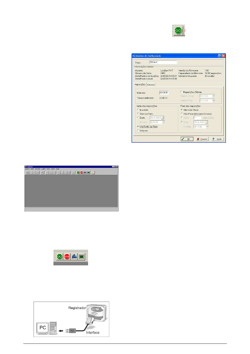
When communication is established, select
The Configuration Parameters screen is displayed. In this screen
the user can define the logger operation mode and also obtain
general information about the device.
Figure 06 – Configuration window
Fields are:
1- Title: In this field, the user identifies the logger by assigning it a
name.
2- General information: Area with information about the logger,
such as Model, Serial Number, Logger Date/Time, PC Date/Time,
firmware version, memory capacity and number of acquisitions
stored in memory, etc.
In this field, time is constantly updated while the communication
between logger and computer is taking place.
4- Readings: Presents a series of parameters that define how
measurements will be.
Interval between readings: Defines the interval between
readings: Minimum interval is 1 (one) second.
Note: When the type of value logged is mean, maximum and
minimum values, the minimum interval is 10 seconds.
In Daily repetitions the user defines the time that daily logs will
take place.
Estimated time: In this parameter, the logger informs the user
how long it will take to occupy the full memory, in the conditions
set up during configuration.
Start of Readings: Readings can be started in one of five
different modes:
•
Immediately: start as soon as programming is considered
to be ready, and is then sent (OK) to the logger.
•
Start via Palm: start with a command sent via Palmtop,
which runs the software Log Chart Palm-OS.
•
Date: readings start at predefined date and time.
•
Through Start Button: starts and interrupts readings by
pressuring the Start button, in the frontal part of the
logger, for two seconds. See Figure 01.
•
Setpoint: measurements start when a temperature
setpoint is reached. In this option, the setpoint value is
defined in the Channels field, where the Alarm parameter
is replaced by setpoint.