Operation – NOVUS Controller N3000 User Manual
Page 4
Controller N3000
NOVUS AUTOMATION
4/9
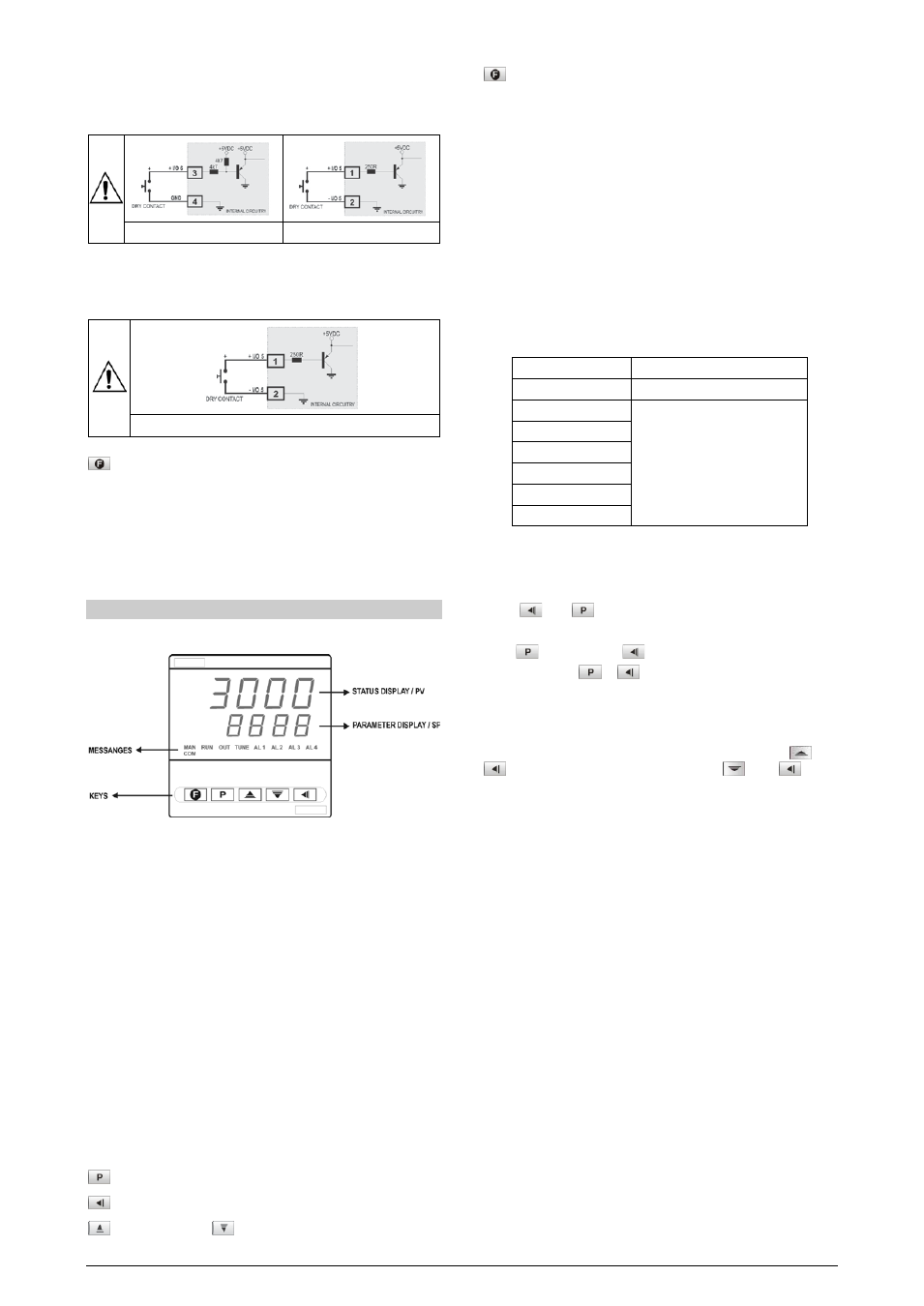
I/O5 and I/O6 can be used as digital inputs, accepting either dry contact
or NPN open collector signals. Figure 7 shows a switch driving the I/O6
digital input. The digital input at I/O5 is driven only by dry contact
signals. Figure 8 shows a typical digital input wiring for I/O5.
Figure 7 – Digital input at I/O6
Figure 8 – Digital input at I/O5
DIGITAL OUTPUT
I/O5 can also be configured as digital output. An example of usage is
shown in Figure 9. I/O5 is electrically isolated from the sensor input.
Figure 9 – I/O5 digital output wiring.
KEY AND DIGITAL INPUT (I/O6) FUNCTIONS
Both the key and the I/O6 digital input can be programmed to execute
functions 7, 8, 9 and 10 shown in Table 2. The key function is
configured in parameter “fFvn”. The digital input function is
configured in parameter IO6.
The digital input can also be configured for function 6: Auto/Manual
mode change.
OPERATION
The front panel is shown in Figure 10.
Figure 10 - Front panel parts
Status display / PV: shows the value of PV (Process Variable).
When in programming mode, shows the parameter name.
Parameter display / SV: shows the SV (Setpoint Variable) value and
the value of other parameters of the controller.
COM Indicator: Flashes when communication messages are sent by
the controller.
TUNE Indicator: Lights during the execution of PID automatic
tunning.
MAN Indicator: Lights when the controller is in manual.
RUN Indicator: Lights when the controller is active, with control and
alarm outputs enabled.
OUT Indicator: For relay or pulse control output, reflects the actual
state of the output. If an analog output is assigned for control, lights
continuously.
A1, A2, A3 and A4 Indicators: Status of the alarms.
- PROG key: used to walk through the menu cycles
- BACK key: go back to the previous displayed parameter
- INCREASE and
- DECREASE keys: Used to change
parameter values
- Programmable FUNCTION Key: Can be assigned to the
special functions described for the f.fvnc parameter.
When the controller is turned on, its firmware version is displayed for
3 seconds, after which the controller starts normal operation. The
values of PV and SV are displayed and the outputs are enabled.
Before the controller is ready to be used in a given process, it
requires some basic configuration, such as:
•
Input type (T/C, Pt100, 4-20 mA,...) at the “tYPE” prompt,
according to Table 1;
•
Output type at “I/O 1”, “I/O 2”,... “I/O 6” prompts (see Table 2);
•
Setpoint variable SV. Set the remaining parameters.
•
PID parameters (or hysteresis for ON/OFF control)
Other functions, including alarms, ramp and soak, timer, digital input,
etc., may be useful for a better system performance. The parameters
are grouped in 7 cycles.
CYCLE
ACCESS
1- Operation
Free access parameters *
2- Tuning
3- R&S Program
4- Alarms
Reserved access parameters **
5- Input Configuration
6- I/Os
7- Calibration
*These parameters can be viewed but not changed if the cycle is
protected.
**Requires a key combination to access the cycle.
Press
and
simultaneously to move from one cycle to
the next one.
Press
to advance and
to go back in the menu cycle.
Keep pressing the
or
key to move fast forward or backward.
At the end of each cycle the controller returns to the operation cycle.
PROGRAM SECURITY
Each menu cycle can be locked (protected) by pressing
and
simultaneously for 3 seconds. Press
and
for 3
seconds to unlock. A short blink of the display confirms the
lock/unlock change.
For further protection, the unlock operation through the keypad may
be disabled by changing the position of an internal strap inside the
controller:
When PROT is OFF, the user is allowed to lock and unlock the
cycles using the keypad as explained above. If PROT is ON, the
cycles lock/unlock operation is disable.