Model dc80t operating instructions, Thermocouple or mv measurement, Thermocouple or mv simulation – NOVUS DC80L User Manual
Page 4
4
3.3. MODEL DC80T OPERATING INSTRUCTIONS
In thermocouple temperature simulation the calibrator generates the voltage as an
actual thermocouple, considering both the simulated temperature (hot joint) and
connection temperature (cold joint). To ensure stated accuracy the user must use
a connection cable between calibrator and calibrated device with the same
thermoelectric properties of the selected thermocouple (extension or
compensation cable).
A K type extension cable (yellow connector) is supplied with the calibrator and
should only be used for K type calibration for maximum accuracy.
Make sure that the appropriate cable with the correct polarity is being used to
avoid large calibration errors.
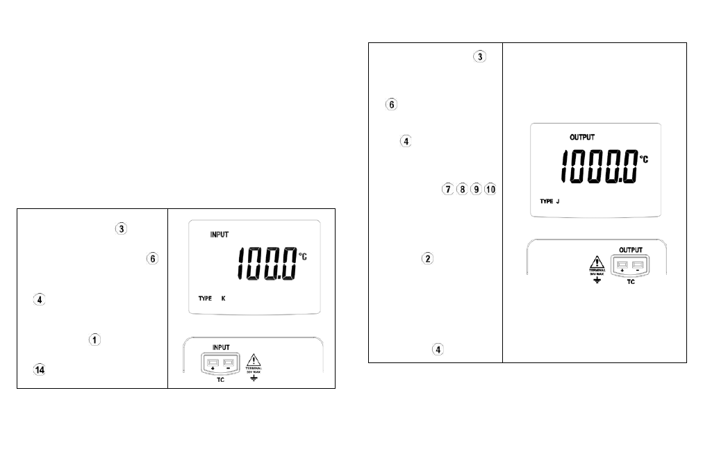
Thermocouple or mV measurement
1. Press the power switch to turn
on the calibrator.
2. Press the INPUT / OUTPUT key
to select INPUT mode.
3. Press the TC TYPE selection key
to configure the instrument to the
desired input type
4. Connect the T/C or mV signal to the
input connector .
5. The measured value is presented in
.
Thermocouple or mV Simulation
1. Press the power switch to
turn on the calibrator.
2. Press the INPUT / OUTPUT key
to select OUTPUT mode.
3. Press the TC TYPE selection
key
to configure the desired
output signal type.
4. Press the increment /
decrement keys
to adjust the value to be
simulated.
5. The simulated signal is
delivered at the output
connector .
6. To change output values, press
the increment / decrement keys
until the desired value is
presented in the display.
Changing to other input types is
accomplished by the TC TYPE
selection key .