Problems with the controller, Finding the controller’s version and serial number, Specifications – NOVUS Controller N480D User Manual
Page 5: Outa / outc relay spst-na: 1.5 a / 240 vac, Outb voltage pulse for ssr, 12 v max. / 20 ma, Outd (rar) 0-20 ma or 4-20 ma, 550 ( max. 31000 levels, isolated, Model identification
N480D Controller
NOVUS AUTOMATION
5/6
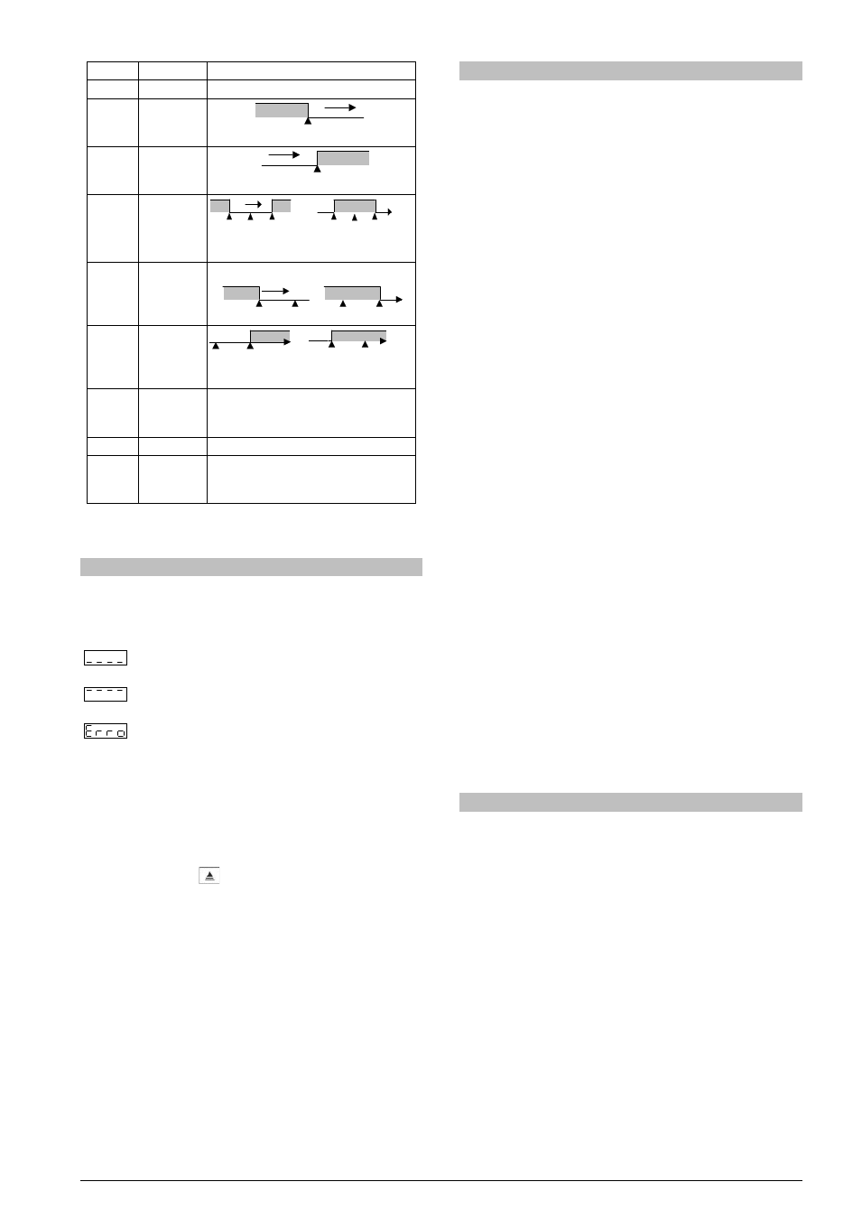
PROMPT
TYPE
ACTION
Off
Disabled
Output is not used as alarm.
Lo
Minimum
value
(Low)
SPAn
PV
ON
Ki
Maximum
value
(High)
SPAn
PV
ON
Dif
Differential
(diFerential)
SV
PV
SV + SPAn
SV - SPAn
ON
ON
SV
PV
SV - SPAn
SV + SPAn
ON
Positive SPAn
Negative SPAn
Difl
Minimum
Differential
(diFerential
Low)
SPAn positivo SPAn negativo
SV
PV
SV - SPAn
ON
SV
PV
SV - SPAn
ON
Difk
Maximum
Differential
(diFerential
High)
SV
SV + SPAn
ON
SV
PV
SV + SPAn
ON
Positive SPAn
Negative SPAn
Ierr
Sensor Break
(input Error)
Activated when the input signal of PV is
interrupted, out of the range limits or
Pt100 in short-circuit.
End.T
End of Level Activate at the end of the level time.
Rs
Event
(ramp and
Soak)
Can be activated at a specific segment
of program.
Table 4 – Alarm functions
Where SPAn refers to Setpoints of Alarm SPA1 and SPA2.
PROBLEMS WITH THE CONTROLLER
Connection errors and inadequate programming are the most common
errors found during the controller operation. A final revision may avoid
loss of time and damages. The controller displays some messages to
help the user identify problems.
: Sensor measuring temperature below the specified
minimum.
: Sensor measuring temperature above the specified
maximum.
: Controller failure or sensor error, examples: Thermocouple
open, Pt100 open in short circuit or poorly connected.
If the “Error” message persists after analysis of the
installation, contact manufacturer informing equipment’s
Serial Number.
FINDING THE CONTROLLER’S VERSION AND SERIAL NUMBER
When the controller is turned on, it shows on its displays for three
seconds its version (review). To see the serial number turn the
controller on holding the
key.
This information is necessary for eventual contact with the controller’s
manufacturer.
SPECIFICATIONS
DIMENSIONS: ........................................ 48 x 48 x 110 mm (1/16 DIN)
........................................................... Approximate Weight: 150 g
CUTOUT IN THE PANEL: .................. 45.5 x 45.5 mm (+0.5 -0.0 mm)
POWER SUPPLY: .................... 100 to 240 Vac/dc (±10 %), 50/60 Hz
Optionally: ....................................................... 24 Vdc/ac (±10 %)
Consumo máximo: ............................................................... 6 VA
ENVIRONMENTAL CONDITIONS:
Operation Temperature: ................................................ 5 to 50 °C
Relative Humidity: .......................................... 80 % max. up 30 ºC
For temperatures above 30 ºC, reduce 3 % for each ºC
Internal Use; Category of installation II, Degree of pollution 2;
altitude < 2000 m.
INPUT .......................... Thermocouples, Pt100 (according to Table 1)
Internal Resolution: ................................... 32767 levels (15 bits)
Resolution of Display: ...... 12000 levels (from -1999 up to 9999)
Rate of input reading: .................................. up to 55 per second
Precision: .. Thermocouples J, K, T, E: 0.25 % of the span ±1 ºC
.................. Thermocouples N, R, S, B: 0.25 % of the span ±3 ºC
............................................................... Pt100: 0.2 % of the span
Input Impedance: ................ Pt100 and thermocouples: >10 MΩ
Measurement of Pt100: ............... Three wires type, (α=0.00385)
with compensation for cable length, excitation current of 0.170 mA.
All input and output types are factory-calibrated. Thermocouples
according to standard NBR 12771 / 99, RTD’s NBR 13773 / 97;
OUTPUTS
OUTA / OUTC .......................... Relay SPST-NA: 1.5 A / 240 Vac,
...................................... General use, resistive load; 100 k cycles
OUTB ......................... Voltage pulse for SSR, 12 V max. / 20 mA
OUTD (RPR/RRR) .........Relay SPDT: 3 A / 250 Vac, general use
OUTD (RAR) ................................................. 0-20 mA or 4-20 mA
550 Ω max. 31000 levels, Isolated
ELECTROMAGNETIC COMPATIBILITY:
........................................ EN 61326-1:1997 and EN 61326-1/A1:1998
SAFETY: ........................... EN61010-1:1993 and EN61010-1/A2:1995
FRONT PANEL: IP65, POLYCARBONATE UL94 V-2;
CASE: IP30, ABS+PC UL94 V-0;
STARTS UP OPERATION AFTER 3 SECONDS CONNECTED TO
THE POWER SUPPLY.
MODEL IDENTIFICATION
The sticker on the controller presents the identification of the model, as
described below.
N480 D - A - B
Where A =
RP: OUTA: Relay; OUTB: Pulse
RPR: OUTA: Relay; OUTB: Pulse; OUTD: Relay
RAR: OUTA: Relay; OUTB: Pulse; OUTD: 0-20 / 4-20 mA
RRR: OUTA: Relay; OUTB: Pulse; OUTC: Relay; OUTD: Relay
Where B= ............................................... 24V for power supply 24 Vdc/ac
............................................ blank: power supply 100~240 Vac/dc